Home » Application » PWM Modulator for Microcontroller Servo Control
PWM Modulator for Microcontroller Servo Control
Microcontrollers are an excellent and inexpensive device for controlling servos. In order to properly control a servo with a microcontroller, it is necessary to learn a few techniques, such as properly generating a control signal for a servo, which the rest of this article will cover. A servo can be thought of as a direct current (DC) motor (which rotates an external motor shaft but provides no way to determine the amount of rotation) with a built-in controller. The control circuitry compares an angular position, determined by a control signal, to the current position of the motor shaft.

The motor shaft's angular position is often determined by a potentiometer, which is rotated by the motor shaft. A potentiometer is a three-terminal resistor whose center connection has variable resistance, usually controlled by a slider or dial. The potentiometer acts as a variable voltage divider. The voltage from the center connection of the potentiometer represents the angular position the motor shaft is in. Other methods to determine angular position and rotation exist for bigger servos, but a potentiometer is the most common for small servos. The built-in controller generates an internal signal from the voltage controlled by the potentiometer, compares it to the control signal, and then provides power to the DC motor to rotate the shaft in the appropriate direction to match the two. Electric servos usually require a pulse-width modulated control signal.
Pulse-width modulation
Often, when controlling an analog device, the ability to drive a signal with variable power (P= I x V) is needed. For example, you may want to adjust the speed of a DC motor or dim a light-emitting diode (LED). This can be a challenge when the signal is generated by a digital device. Different methods to convert a digital signal to an analog signal exist, one of which is a digital-to-analog converter. Using a converter will add complexity to a project, so generating a variable power signal with existing circuitry is desirable to reduce the number of components.
An easy method to vary the power using a digital signal, when an analog signal isn't available, is by a method called pulse-width modulation (PWM). Instead of controlling the current or voltage of a signal, a pulse-width-modulated signal works by repeatedly pulsing the digital signal high and low at a fast rate. When sufficiently fast, the signal creates an effective average voltage. A shorter PWM period (the length between the rising edges) will create a cleaner average voltage, because the signal is effectively less (i.e, less discharge from the capacitance in the line is needed to smooth the signal), but the minimum period will be limited by the speed of the device generating the signal.
The period of the PWM signal is usually constant for a given application, and the high pulse width (the duration of the signal being driven high within one period) is usually variable, so that the average voltage of the signal can be changed. The ratio of high pulse width to period of the signal is called the duty cycle.

The power through a device is proportional to the voltage supplied. Therefore, to decrease the power usage of a device (to dim an LED or to slow a motor), the duty cycle of the PWM signal should be decreased. A PWM signal can be used to limit the power to a device to save energy. This technique is used in many portable devices which have limited battery power. For example, wave a device with an LED back and forth in your hand and you will often see a strobe light effect instead of a straight streak. This blinking is from the pulse-width-modulated signal turning the LED on and off. The blinking cannot normally be perceived by the human eye when the LED is stationary, since it is blinking at a rate faster than the eye can perceive. When moving, the discrete flashes become visible because the LED is only lit up at certain positions as it moves.
Some devices, such as servos, do not rely on the power of the signal limited by PWM but instead use the width of the high pulses to transmit information. This is also used by infrared remote controls to transmit data to control a television or radio.
Pulse-width-modulated signals may be generated from many digital devices, even ones as simple as an index pensive timer integrated circuit (such as the 8-pin 555 timer). A versatile yet inexpensive solution for many robotics hobbyists is to use micro controller for PWM generation. Using a micro controller has the added advantage of containing all of the control circuitry (needed for analyzing and responding to input) for a simple robot on a single chip.
Controlling a servo
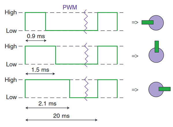
Most servos, including the Hitec RCD USA, Inc. HS-322HD demonstrated here, have three pins: power, ground, and a control signal. The control signal is a pulse-width modulated input signal whose high pulse width determines the servo's angular position, as shown in Fig. 3. Internally, the servo compares the PWM control signal to an internally generated signal, whose pulse widths are controlled by the potentiometer (which determines the shaft angle) and matches the pulse widths by rotating the motor shaft. For the HS- 322HD, power can be between 48V DC (volts of direct current) and 6 V DC. Since the control signal (which draws a maximum of about 20 mA) does not drive the motor directly, an additional benefit of using a servo is that the PIC (whose output pins can drive up to 25 mA) can drive the control signal directly. Most motors draw more than 25 mA of current for operation and, therefore, must be indirectly connected to the PIC through a current amplifying device, like an H bridge or a transistor.
Signal generation with a PIC
Pulse- width modulated signal generation is easy to implement on micro controllers. All micro controllers will be able to generate a PWM signal, but the more expensive and elaborate ones provide hardware to make PWM generation easier, freeing up more processor time to run other tasks. An inexpensive and easily obtainable micro controller, such as the PIC micro 18F452, provides enough hardware to implement PWM generation using a few different methods, depending on the needs of the application.
The simplest but most processor- intensive method to create a PWM signal is manually comparing a “count” to a variable that describes how long the high pulse width should be. When the count is less than the pulse width variable, the PWM signal is driven high; otherwise, it is driven low.
After the PWM period has elapsed, the count can be reset and the process started over. The PWM period will be the same as the time it takes the PIC to run your code. To increase the length of the PWM period, loops can be used to create delay. This method will work on the simplest of PICs but leaves little processor time to do anything else. A couple variations exist and can be used if the PIC includes the necessary hardware. A timer can be used and polled at intervals in between code to determine if the PWM signal needs to be updated. Another solution is to have the PIC update the PWM signal on a timer overflow interrupt. This guarantees that the PWM signal will be updated at specific intervals, while most of the processor time can be used for other tasks.
The least processor-intensive method is to use a built-in PWM module if your micro controller has one. When enabled, the PWM module will automatically generate a PWM signal with a period and duty cycle specified in control registers on the PIC. Depending on the micro controller you are using and the speed it is running at, the built-in PWM module might not support a large enough period needed for the device you are using, such as for a servo motor (which commonly has a period of 20MS). In that case, you will want to use one of the previously mentioned methods to generate a longer PWM signal.
Pulse-width modulation
Often, when controlling an analog device, the ability to drive a signal with variable power (P= I x V) is needed. For example, you may want to adjust the speed of a DC motor or dim a light-emitting diode (LED). This can be a challenge when the signal is generated by a digital device. Different methods to convert a digital signal to an analog signal exist, one of which is a digital-to-analog converter. Using a converter will add complexity to a project, so generating a variable power signal with existing circuitry is desirable to reduce the number of components.
An easy method to vary the power using a digital signal, when an analog signal isn't available, is by a method called pulse-width modulation (PWM). Instead of controlling the current or voltage of a signal, a pulse-width-modulated signal works by repeatedly pulsing the digital signal high and low at a fast rate. When sufficiently fast, the signal creates an effective average voltage. A shorter PWM period (the length between the rising edges) will create a cleaner average voltage, because the signal is effectively less (i.e, less discharge from the capacitance in the line is needed to smooth the signal), but the minimum period will be limited by the speed of the device generating the signal.
The period of the PWM signal is usually constant for a given application, and the high pulse width (the duration of the signal being driven high within one period) is usually variable, so that the average voltage of the signal can be changed. The ratio of high pulse width to period of the signal is called the duty cycle.
Some devices, such as servos, do not rely on the power of the signal limited by PWM but instead use the width of the high pulses to transmit information. This is also used by infrared remote controls to transmit data to control a television or radio.
Pulse-width-modulated signals may be generated from many digital devices, even ones as simple as an index pensive timer integrated circuit (such as the 8-pin 555 timer). A versatile yet inexpensive solution for many robotics hobbyists is to use micro controller for PWM generation. Using a micro controller has the added advantage of containing all of the control circuitry (needed for analyzing and responding to input) for a simple robot on a single chip.
Controlling a servo
Most servos, including the Hitec RCD USA, Inc. HS-322HD demonstrated here, have three pins: power, ground, and a control signal. The control signal is a pulse-width modulated input signal whose high pulse width determines the servo's angular position, as shown in Fig. 3. Internally, the servo compares the PWM control signal to an internally generated signal, whose pulse widths are controlled by the potentiometer (which determines the shaft angle) and matches the pulse widths by rotating the motor shaft. For the HS- 322HD, power can be between 48V DC (volts of direct current) and 6 V DC. Since the control signal (which draws a maximum of about 20 mA) does not drive the motor directly, an additional benefit of using a servo is that the PIC (whose output pins can drive up to 25 mA) can drive the control signal directly. Most motors draw more than 25 mA of current for operation and, therefore, must be indirectly connected to the PIC through a current amplifying device, like an H bridge or a transistor.
Pulse- width modulated signal generation is easy to implement on micro controllers. All micro controllers will be able to generate a PWM signal, but the more expensive and elaborate ones provide hardware to make PWM generation easier, freeing up more processor time to run other tasks. An inexpensive and easily obtainable micro controller, such as the PIC micro 18F452, provides enough hardware to implement PWM generation using a few different methods, depending on the needs of the application.
The simplest but most processor- intensive method to create a PWM signal is manually comparing a “count” to a variable that describes how long the high pulse width should be. When the count is less than the pulse width variable, the PWM signal is driven high; otherwise, it is driven low.
After the PWM period has elapsed, the count can be reset and the process started over. The PWM period will be the same as the time it takes the PIC to run your code. To increase the length of the PWM period, loops can be used to create delay. This method will work on the simplest of PICs but leaves little processor time to do anything else. A couple variations exist and can be used if the PIC includes the necessary hardware. A timer can be used and polled at intervals in between code to determine if the PWM signal needs to be updated. Another solution is to have the PIC update the PWM signal on a timer overflow interrupt. This guarantees that the PWM signal will be updated at specific intervals, while most of the processor time can be used for other tasks.
The least processor-intensive method is to use a built-in PWM module if your micro controller has one. When enabled, the PWM module will automatically generate a PWM signal with a period and duty cycle specified in control registers on the PIC. Depending on the micro controller you are using and the speed it is running at, the built-in PWM module might not support a large enough period needed for the device you are using, such as for a servo motor (which commonly has a period of 20MS). In that case, you will want to use one of the previously mentioned methods to generate a longer PWM signal.
Post a Comment:
You may also like:
Category
Featured Articles
Servo Motor in Medical Industry
 With the continuous development of technology, servo motors are being used more and more widely in medical equipment. Servo ...
With the continuous development of technology, servo motors are being used more and more widely in medical equipment. Servo ...Servo System in CNC Machine Tools
 As the actuator of CNC machine tools, servo system integrates power electronics, control, drive and protection, and with the ...
As the actuator of CNC machine tools, servo system integrates power electronics, control, drive and protection, and with the ...Equation Derivation for Servo Motor
 In the analysis of electric servo drive motors , the equations for the motor indicates the presence of two time constants. One is ...
In the analysis of electric servo drive motors , the equations for the motor indicates the presence of two time constants. One is ...Servo Drives for Electric Mobility
 Servo drives play a crucial role in electric mobility applications, providing precise control of electric motors for various ...
Servo drives play a crucial role in electric mobility applications, providing precise control of electric motors for various ...Servo Motor in Food Industry
 In the ever-evolving landscape of the food industry, technological advancements play a pivotal role in enhancing efficiency, ...
In the ever-evolving landscape of the food industry, technological advancements play a pivotal role in enhancing efficiency, ...