Home » AC Servo Motor » How to Wire an AC Servo Motor?
How to Wire an AC Servo Motor?
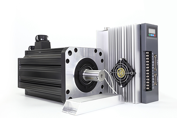
A servo motor is a type of motor that allows precise control of position, speed, and acceleration through a controller. The controller of the servo motor adjusts the drive current of the motor according to the position information fed back from the encoder, thus controlling the position and motion of the motor. In order for servo motors to operate better, it is necessary to understand the wiring method. Before wiring Do not bundle power and signal cables together or run them in the same pipe. Keep a distance of at least 300 mm between the power and signal cables. Signal lines and encoder feedback lines should be selected as twisted pair shielded lines or multi-core twisted pair shielded lines.
The maximum length of the input line for reference is 3 meters and the maximum length of the encoder feedback line is 20 meters. Do not touch the power terminals for 5 minutes after turning off the power, as high voltage may still be present in the servo drive.
Interface for Line Driver Output Circuit
The amount of two-phase (phase A and phase B) pulse output signals (PAO/PAO, PBO/PBO) and zero-point pulse signals (PCO/PCO) are output via line-driver output circuits. Normally, the servo drive uses this output circuit in speed control to comprise the servo position control system at the host controller. Connect the line-driver output circuit through a line receiver circuit at the host controller.
Interface for Sequence Output Circuit
Photo coupler output circuits are used for servo alarm (ALM), servo ready (S-RDY), and other sequence output signal circuits. Connect a photo coupler output circuit through a relay circuit.

Power supply wiring: the servo motor needs to be powered by a DC power supply, and its positive and negative poles are connected to the positive and negative poles of the power supply respectively.
Control signal wiring: the control signal of the servo motor needs to be provided to the driver, and converted and amplified by the driver.
Usually, the control signal includes pulse, direction and enable signals. The pulse signal is used to control the angle and speed of motor rotation, the direction signal indicates the direction of motor rotation, and the enable signal is used to start or stop the motor.
Encoder wiring: In order to realize more accurate position control, servo motors are usually equipped with an encoder, which is used to monitor the position and motion status of the motor. The encoder generally has two output signals A and B, through which the position and direction of the motor can be determined. Connect the encoder output signals with the controller to realize precise position control.
If the AC servo motor is grounded via the machine, a switching noise current will flow from the servo drive main circuit through the servo motor stray capacitance. Always connect servo motor frame terminal FG to the servo drive ground terminal. Also, be sure to ground the ground terminal.
The maximum length of the input line for reference is 3 meters and the maximum length of the encoder feedback line is 20 meters. Do not touch the power terminals for 5 minutes after turning off the power, as high voltage may still be present in the servo drive.
Interface for Line Driver Output Circuit
The amount of two-phase (phase A and phase B) pulse output signals (PAO/PAO, PBO/PBO) and zero-point pulse signals (PCO/PCO) are output via line-driver output circuits. Normally, the servo drive uses this output circuit in speed control to comprise the servo position control system at the host controller. Connect the line-driver output circuit through a line receiver circuit at the host controller.
Interface for Sequence Output Circuit
Photo coupler output circuits are used for servo alarm (ALM), servo ready (S-RDY), and other sequence output signal circuits. Connect a photo coupler output circuit through a relay circuit.
Power supply wiring: the servo motor needs to be powered by a DC power supply, and its positive and negative poles are connected to the positive and negative poles of the power supply respectively.
Control signal wiring: the control signal of the servo motor needs to be provided to the driver, and converted and amplified by the driver.
Usually, the control signal includes pulse, direction and enable signals. The pulse signal is used to control the angle and speed of motor rotation, the direction signal indicates the direction of motor rotation, and the enable signal is used to start or stop the motor.
Encoder wiring: In order to realize more accurate position control, servo motors are usually equipped with an encoder, which is used to monitor the position and motion status of the motor. The encoder generally has two output signals A and B, through which the position and direction of the motor can be determined. Connect the encoder output signals with the controller to realize precise position control.
If the AC servo motor is grounded via the machine, a switching noise current will flow from the servo drive main circuit through the servo motor stray capacitance. Always connect servo motor frame terminal FG to the servo drive ground terminal. Also, be sure to ground the ground terminal.
Post a Comment:
You may also like:
Category
Featured Articles
What is Operation Principle of AC ...
 The output torque of the servo motor is proportional to the current that flows in the motor. Because the servo amplifier normally ...
The output torque of the servo motor is proportional to the current that flows in the motor. Because the servo amplifier normally ...AC Servo Motor: Structure, Working and ...
 AC servo motor is a type of motor widely used in various industrial and commercial fields. It features high precision,fast ...
AC servo motor is a type of motor widely used in various industrial and commercial fields. It features high precision,fast ...What is Position Control by AC Servo?
 The methods for stopping a moving object with prescribed accuracy at a fixed position consist of a mechanical method and an ...
The methods for stopping a moving object with prescribed accuracy at a fixed position consist of a mechanical method and an ...How to Wire an AC Servo Motor?
A servo motor is a type of motor that allows precise control of position, speed, and acceleration through a controller. The ...
A servo motor is a type of motor that allows precise control of position, speed, and acceleration through a controller. The ...