Home » Application » Equation Derivation for Servo Motor
Equation Derivation for Servo Motor
In the analysis of electric servo drive motors, the equations for the motor indicates the presence of two time constants. One is a mechanical time constant and the other is an electrical time constant. Commercial servo motor specifications usually list these two time constants. However, it should be cautioned that these two time constants as given in the specifications are for the motor alone with no load inertia connected to the motor shaft. Since these two time constants are part of the motor block diagram used in servo analysis, it is important to know the real value of the time constants under actual load conditions.
There are two types of servo motors to consider. The first is the classical dc servo motor and the second is the ac servo motor often referred to as a brushless dc motor.
A derivation of the motor equations and the electrical and mechanical motor time constants will be discussed for the dc motor followed by the ac motor. The dc motor equivalent diagram is:

Where:
ei= Applied voltage (volts)
ia= Armature current (amps)
Jt= Total inertia of motor armature plus load (lb-in-sec2)
Ke= Motor voltage constant (v/rad/sec)
Kt= Motor torque constant (lb-in/A)
La= Motor winding inductance (Henries)
Ra= Armature resistance (ohms)
TL= Load torque (lb-in)
Vm= Motor velocity (rad/sec)
α= Acceleration (rad/sec2)
The steady state (dc) equations are:
ei= iaRa+KeVm (Voltage equation)
t= Torque= iaKt=Jα (Torque equation)
For the general case, the differential equations are:
ei= iaRa+La(dia/dt)+KeVm
Laplace operator S=d/dt
ei=Raia + LaSia + KeVm
ei=(Ra + LaS)ia + KeVm
ei=[(La/Ra)S+1]Raia+ KeVm
Also:
T=Ktia=Jtα=JtVmS
ia=T/Kt= JtVmS/Kt
Combining equations gives:
ei-KeVm=[(La/Ra)S+1]Ra[(JtVmS)/Kt]
Rearranging results in:
[(ei-KeVm)Kt]/{[(La/Ra)S+1]RaJtS}=Vm
This last equation can be represented in block diagram form as:

The closed loop equation C/R=G/(1+GH) for the above block diagram is:
Vm/ei=Kt/{RaJtS[(La/Ra)S+1]+KeKt}
Rearranging gives:
Vm/ei=Kt/[RaJt(La/Ra)S2+JtRaS+KeKt]
Dividing by KeKt gives:
Vm/ei=(1/Ke)/[(RaJt/KeKt)( La/Ra)S2+( RaJt/KeKt)S+1]
From the last equation, the motor mechanical time constant, Tm, is:
Tm= RaJt/KeKt [sec]
The total inertia, Jr, is the sum of the reflected inertia to the motor shaft plus the motor inertia. The resistance, Ra, is the motor winding resistance plus the external circuit resistance. Thus the motor mechanical time constant is summarized as:
Tm=ΣRaJt/KeKt
Also, the servo motor electrical time constant is:
Te=La/ΣRa [sec]
Therefore, the closed loop motor equation can be expressed as:
Vm/ei=(1/Ke)/(TmTeS2+TmS+1)
From the general equation for a quadratic:
(S2/ωm2)+(2δS/ωm)+1
Where:
ωm=(1/TmTe)-2
The damping factor is:
δ=0.5 Tmωm =0.5Tm(1/TmTe)-2=0.5(Tm/Te)-2
The mechanical and electrical time constants for a brushless dc motor have the same basic equations with some variations. For a brushless dc motor with a wye connected motor, the electrical circuit is:
The mechanical time constant is:
Tm=ΣRphaseJtotal/Ke(phase)Kt [sec]
Where:
Ke(phase)=Motor voltage constant=Ke(L-L)/1.73 [(V-sec)/RAD]
Kt= Motor torque constant [(Ib-in)/A]
Rm(L-L)=Motor resistance [ohms]
ΣRm(L-L)=Total motor circuit resistance=1.35 Rm(L-L) [ohms]
ΣRm(phase)=ΣRm(L-L)×0.5=[ohms]
LL-L=Motor inductance= [Henries]
JTOTAL=Motor armature inertia plus the reflected load inertia at the motor shaft= [Ib-in-sec2]
Most manufacturers give the electrical parameters in line-to-line values. Thus some of these values must be converted to the phase values as shown above. Summarizing, the mechanical time constant can be computed as:
Tm=[Σ(RL-L/2)JTOTAL]/KtKe(L-L)/1.73 [sec] = 0.86(RL-LJtotal motor)/Ke(L-L)Kt
The electrical time constant for the brushless dc motor is computed as:
Te=Total inductive path/ Total resistive path= LL-L/ΣRm(L-L) [sec]
Another factor affecting the mechanical time constant is the temperature. Most manufacturers specify the servo parameters at 25° C (cold rating). This implies that the magnet and wires are both at room temperature. However, the motors used in industry will operate hotter which could reach a magnet temperature of 80° C to 90°C in a 40° C ambient. The winding temperature is considerably more than that. Some means must be used to compensate for the motor parameters rated at 25° C. For those manufacturers that offer the hot rating on motor specification parameters, they should be used to calculate the time constants. The parameters of motor resistance, torque constant, and voltage constant should be adjusted, if needed, for the hot rating. The motor resistance will increase; the torque constant and voltage constant will decrease. However, contrary to their implied name both time constants are not of constant value. Rather, they are both functions of the motor’s operating temperature.
There are two types of servo motors to consider. The first is the classical dc servo motor and the second is the ac servo motor often referred to as a brushless dc motor.
A derivation of the motor equations and the electrical and mechanical motor time constants will be discussed for the dc motor followed by the ac motor. The dc motor equivalent diagram is:
Where:
ei= Applied voltage (volts)
ia= Armature current (amps)
Jt= Total inertia of motor armature plus load (lb-in-sec2)
Ke= Motor voltage constant (v/rad/sec)
Kt= Motor torque constant (lb-in/A)
La= Motor winding inductance (Henries)
Ra= Armature resistance (ohms)
TL= Load torque (lb-in)
Vm= Motor velocity (rad/sec)
α= Acceleration (rad/sec2)
The steady state (dc) equations are:
ei= iaRa+KeVm (Voltage equation)
t= Torque= iaKt=Jα (Torque equation)
For the general case, the differential equations are:
ei= iaRa+La(dia/dt)+KeVm
Laplace operator S=d/dt
ei=Raia + LaSia + KeVm
ei=(Ra + LaS)ia + KeVm
ei=[(La/Ra)S+1]Raia+ KeVm
Also:
T=Ktia=Jtα=JtVmS
ia=T/Kt= JtVmS/Kt
Combining equations gives:
ei-KeVm=[(La/Ra)S+1]Ra[(JtVmS)/Kt]
Rearranging results in:
[(ei-KeVm)Kt]/{[(La/Ra)S+1]RaJtS}=Vm
This last equation can be represented in block diagram form as:
The closed loop equation C/R=G/(1+GH) for the above block diagram is:
Vm/ei=Kt/{RaJtS[(La/Ra)S+1]+KeKt}
Rearranging gives:
Vm/ei=Kt/[RaJt(La/Ra)S2+JtRaS+KeKt]
Dividing by KeKt gives:
Vm/ei=(1/Ke)/[(RaJt/KeKt)( La/Ra)S2+( RaJt/KeKt)S+1]
From the last equation, the motor mechanical time constant, Tm, is:
Tm= RaJt/KeKt [sec]
The total inertia, Jr, is the sum of the reflected inertia to the motor shaft plus the motor inertia. The resistance, Ra, is the motor winding resistance plus the external circuit resistance. Thus the motor mechanical time constant is summarized as:
Tm=ΣRaJt/KeKt
Also, the servo motor electrical time constant is:
Te=La/ΣRa [sec]
Therefore, the closed loop motor equation can be expressed as:
Vm/ei=(1/Ke)/(TmTeS2+TmS+1)
From the general equation for a quadratic:
(S2/ωm2)+(2δS/ωm)+1
Where:
ωm=(1/TmTe)-2
The damping factor is:
δ=0.5 Tmωm =0.5Tm(1/TmTe)-2=0.5(Tm/Te)-2
The mechanical and electrical time constants for a brushless dc motor have the same basic equations with some variations. For a brushless dc motor with a wye connected motor, the electrical circuit is:
The mechanical time constant is:
Tm=ΣRphaseJtotal/Ke(phase)Kt [sec]
Where:
Ke(phase)=Motor voltage constant=Ke(L-L)/1.73 [(V-sec)/RAD]
Kt= Motor torque constant [(Ib-in)/A]
Rm(L-L)=Motor resistance [ohms]
ΣRm(L-L)=Total motor circuit resistance=1.35 Rm(L-L) [ohms]
ΣRm(phase)=ΣRm(L-L)×0.5=[ohms]
LL-L=Motor inductance= [Henries]
JTOTAL=Motor armature inertia plus the reflected load inertia at the motor shaft= [Ib-in-sec2]
Most manufacturers give the electrical parameters in line-to-line values. Thus some of these values must be converted to the phase values as shown above. Summarizing, the mechanical time constant can be computed as:
Tm=[Σ(RL-L/2)JTOTAL]/KtKe(L-L)/1.73 [sec] = 0.86(RL-LJtotal motor)/Ke(L-L)Kt
The electrical time constant for the brushless dc motor is computed as:
Te=Total inductive path/ Total resistive path= LL-L/ΣRm(L-L) [sec]
Another factor affecting the mechanical time constant is the temperature. Most manufacturers specify the servo parameters at 25° C (cold rating). This implies that the magnet and wires are both at room temperature. However, the motors used in industry will operate hotter which could reach a magnet temperature of 80° C to 90°C in a 40° C ambient. The winding temperature is considerably more than that. Some means must be used to compensate for the motor parameters rated at 25° C. For those manufacturers that offer the hot rating on motor specification parameters, they should be used to calculate the time constants. The parameters of motor resistance, torque constant, and voltage constant should be adjusted, if needed, for the hot rating. The motor resistance will increase; the torque constant and voltage constant will decrease. However, contrary to their implied name both time constants are not of constant value. Rather, they are both functions of the motor’s operating temperature.
Post a Comment:
You may also like:
Category
Featured Articles
Servo Motor in Food Industry
 In the ever-evolving landscape of the food industry, technological advancements play a pivotal role in enhancing efficiency, ...
In the ever-evolving landscape of the food industry, technological advancements play a pivotal role in enhancing efficiency, ...Servo Drives for Electric Mobility
 Servo drives play a crucial role in electric mobility applications, providing precise control of electric motors for various ...
Servo drives play a crucial role in electric mobility applications, providing precise control of electric motors for various ...Servo Motor in Medical Industry
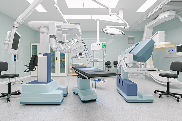 With the continuous development of technology, servo motors are being used more and more widely in medical equipment. Servo ...
With the continuous development of technology, servo motors are being used more and more widely in medical equipment. Servo ...Servo System in CNC Machine Tools
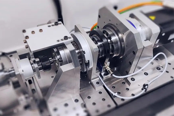 As the actuator of CNC machine tools, servo system integrates power electronics, control, drive and protection, and with the ...
As the actuator of CNC machine tools, servo system integrates power electronics, control, drive and protection, and with the ...Equation Derivation for Servo Motor
In the analysis of electric servo drive motors , the equations for the motor indicates the presence of two time constants. One is ...
In the analysis of electric servo drive motors , the equations for the motor indicates the presence of two time constants. One is ...