Home » Application » AC Servo Motors Used in Relay Application
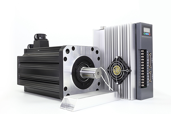
AC Servo Motors Used in Relay Application
The following types of a-c motors are suitable for relay applications:
(a) Split-phase, reluctance-type motors
(b) Series (universal) motors
(c) Torque motors
(d) 2-phase motors
(e) 3-phase motors, for high-power operation
(f) Shaded-pole motors
In the usual application, the servo motor must be reversible and have a starting torque about as large as the running torque or a little larger. High starting torque may be obtained from standard-design motors by increasing rotor resistance. This can be achieved by reducing the thickness of the rotor end piece. Shaded-pole motors can be used in pairs to obtain reversible operation---one motor for clockwise rotation, the other for counter-clockwise rotation.

Typical relay-servo circuits
The series (universal) motor can be used with an AC supply by employing the circuits. Two-phase servo motors can be relay-controlled by using a circuit such as that shown in the following picture. The latter circuit is also usable with wound-shading-coil AC motors. The only damping present is the inherent damping of the motor. Proper choice of circuit elements will bring the motor to a dead stop from full speed within one revolution from the instant the relay contacts connect in the braking circuit. Capacitor C1 can be an electrolytic clement. However, capacitor C2 should be an oil-filled unit, not an AC electrolytic that is designed only for infrequent service such as starting.

Typical 2-phase servo motor
The static torque-speed curves of a typical 2-phase servomotor are shown in above picture. These curves can be used to determine the motor parameters that influence dynamic performance.
Analysis of relay servos can be accomplished by either of two methods: the describing function approach; or the phase-plane method. In each case, the objective is to determine the motor-speed response from an arbitrary initial speed to full speed, or a dead stop. Such responses may be calculated from the speed-torque curve of the motor used in the servo.
At present, the 2-phase servo motor is the type used in servomechanism more often than any other type. The effect of electrical transients caused by winding inductance and resistance is negligible in most applications. Where this effect is important, an additional time constant can be introduced to account for the effect. The break frequency associated with this time constant is in the order of 400 to 800 radians/sec for 60-cycle motors.
Equations
The curves may be used to evaluate the partial derivatives in the representation of the motor as a torque source having some associated damping. The equation is
dT=[(əT/Tmax)/(əE/Emax)][Tmax/Emax]dE+[(əT/Tmax)/(əΩ/Ωsync)][Tmax/Ωsync]dΩ
Where
(əT/Tmax)/(əE/Emax)=non dimensional torque gain
(əT/Tmax)/(əΩ/Ωsync)=non dimensional torque damping
Tmax=stall torque with full motor excitation
Emax=rated reference voltage
An approximate method of obtaining the damping constant OT/an from the manufacturer's curve (which is almost universally made for full motor excitation) is to divide the damping by two (damping measured at the stall and with rated motor excitation).
The resultant damping is pertinent for low control-winding voltages. The torque gain can be derived from the manufacturer's curve by dividing the stall torque at full excitation by the full excitation voltage. Stall torque is theoretically linear with applied voltage.
Alternatives
If more partial-coefficient information is desired, obtain the torque-speed curves for the motor to be used, measured at full and also at partial excitation. These curves can be obtained from the manufacturer or measured by the designer. The desired partial derivatives can be measured from these curves. A third method is to obtain the curves by calculation from the curve for full, rated excitation. This calculation can be performed by using a symmetrical component voltage. It is necessary to have the torque-speed curve for negative as well as positive speeds. The manufacturer's curve for positive speeds can be extrapolated to negative speeds by assuming a power-series representation of the given non-dimensional torque-speed curve:
The “a” coefficients can be evaluated by choosing five points on the given curve and finding a set of a’s consistent with these five value. For less accurate results, the higher-power coefficients can be discarded.
(a) Split-phase, reluctance-type motors
(b) Series (universal) motors
(c) Torque motors
(d) 2-phase motors
(e) 3-phase motors, for high-power operation
(f) Shaded-pole motors
In the usual application, the servo motor must be reversible and have a starting torque about as large as the running torque or a little larger. High starting torque may be obtained from standard-design motors by increasing rotor resistance. This can be achieved by reducing the thickness of the rotor end piece. Shaded-pole motors can be used in pairs to obtain reversible operation---one motor for clockwise rotation, the other for counter-clockwise rotation.
Typical relay-servo circuits
The series (universal) motor can be used with an AC supply by employing the circuits. Two-phase servo motors can be relay-controlled by using a circuit such as that shown in the following picture. The latter circuit is also usable with wound-shading-coil AC motors. The only damping present is the inherent damping of the motor. Proper choice of circuit elements will bring the motor to a dead stop from full speed within one revolution from the instant the relay contacts connect in the braking circuit. Capacitor C1 can be an electrolytic clement. However, capacitor C2 should be an oil-filled unit, not an AC electrolytic that is designed only for infrequent service such as starting.
Typical 2-phase servo motor
The static torque-speed curves of a typical 2-phase servomotor are shown in above picture. These curves can be used to determine the motor parameters that influence dynamic performance.
Analysis of relay servos can be accomplished by either of two methods: the describing function approach; or the phase-plane method. In each case, the objective is to determine the motor-speed response from an arbitrary initial speed to full speed, or a dead stop. Such responses may be calculated from the speed-torque curve of the motor used in the servo.
At present, the 2-phase servo motor is the type used in servomechanism more often than any other type. The effect of electrical transients caused by winding inductance and resistance is negligible in most applications. Where this effect is important, an additional time constant can be introduced to account for the effect. The break frequency associated with this time constant is in the order of 400 to 800 radians/sec for 60-cycle motors.
Equations
The curves may be used to evaluate the partial derivatives in the representation of the motor as a torque source having some associated damping. The equation is
dT=[(əT/Tmax)/(əE/Emax)][Tmax/Emax]dE+[(əT/Tmax)/(əΩ/Ωsync)][Tmax/Ωsync]dΩ
Where
(əT/Tmax)/(əE/Emax)=non dimensional torque gain
(əT/Tmax)/(əΩ/Ωsync)=non dimensional torque damping
Tmax=stall torque with full motor excitation
Emax=rated reference voltage
An approximate method of obtaining the damping constant OT/an from the manufacturer's curve (which is almost universally made for full motor excitation) is to divide the damping by two (damping measured at the stall and with rated motor excitation).
The resultant damping is pertinent for low control-winding voltages. The torque gain can be derived from the manufacturer's curve by dividing the stall torque at full excitation by the full excitation voltage. Stall torque is theoretically linear with applied voltage.
Alternatives
If more partial-coefficient information is desired, obtain the torque-speed curves for the motor to be used, measured at full and also at partial excitation. These curves can be obtained from the manufacturer or measured by the designer. The desired partial derivatives can be measured from these curves. A third method is to obtain the curves by calculation from the curve for full, rated excitation. This calculation can be performed by using a symmetrical component voltage. It is necessary to have the torque-speed curve for negative as well as positive speeds. The manufacturer's curve for positive speeds can be extrapolated to negative speeds by assuming a power-series representation of the given non-dimensional torque-speed curve:
The “a” coefficients can be evaluated by choosing five points on the given curve and finding a set of a’s consistent with these five value. For less accurate results, the higher-power coefficients can be discarded.
Post a Comment:
You may also like:
Category
Featured Articles
Servo Motor in Food Industry
 In the ever-evolving landscape of the food industry, technological advancements play a pivotal role in enhancing efficiency, ...
In the ever-evolving landscape of the food industry, technological advancements play a pivotal role in enhancing efficiency, ...Servo Drives for Electric Mobility
 Servo drives play a crucial role in electric mobility applications, providing precise control of electric motors for various ...
Servo drives play a crucial role in electric mobility applications, providing precise control of electric motors for various ...Servo Motor in Medical Industry
 With the continuous development of technology, servo motors are being used more and more widely in medical equipment. Servo ...
With the continuous development of technology, servo motors are being used more and more widely in medical equipment. Servo ...Equation Derivation for Servo Motor
 In the analysis of electric servo drive motors , the equations for the motor indicates the presence of two time constants. One is ...
In the analysis of electric servo drive motors , the equations for the motor indicates the presence of two time constants. One is ...Servo System in CNC Machine Tools
 As the actuator of CNC machine tools, servo system integrates power electronics, control, drive and protection, and with the ...
As the actuator of CNC machine tools, servo system integrates power electronics, control, drive and protection, and with the ...