How to Center a RC Servo?
A servo is a mechanical motorized device that can be instructed to move the output shaft attached to a servo wheel or arm to a specified position. Inside the servo box is a DC motor mechanically linked to a position feedback potentiometer, gearbox, electronic feedback control loop circuitry and motor drive electronic circuit.
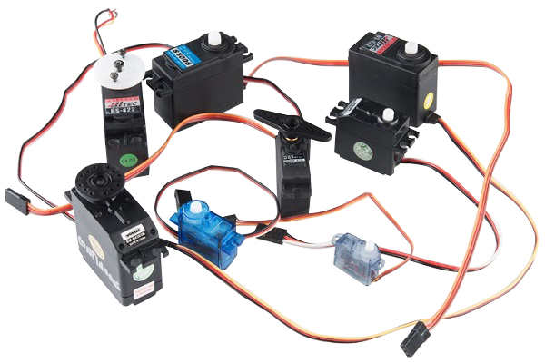
A typical R/C servo looks like a plastic rectangular box with a rotary shaft coming up and out the top of the box and three electrical wires out of the servo side to a plastic 3 pin connector. Attached to the output shaft out the top of the box is a servo wheel or Arm. These wheels or arms are usually a plastic part with holes in it for attaching push / pull rods, ball joints or other mechanical linkage devices to the servo. The three electrical connection wires out of the side are V- (Ground), V+ (Plus voltage) and S Control (Signal). The control S (Signal) wire receives Pulse Width Modulation (PWM) signals sent from an external controller and is converted by the servo on board circuitry to operate the servo.

Servo Centering
RC servos are usually mechanically stopped from moving at full rotation. They have limited rotation through a mechanical, plastic block on the internal gearing and can rotate about 90 to 180 degrees or less only. Servos are unable to continually rotate and usually can't be used for driving rotating wheels. A servos precision positioning makes them ideal for robotics and animatronics, since servos are self contained with control loop circuitry, drive circuits, servo position, speed control, and are very easy to control by an external device such as a electronic servo controller board used in animatronic character and robotic applications.
Servos are dynamic devices that when instructed to move position, will actively move to hold the position, If for example a servo is instructed to move in the clockwise position and an external force is present and pushing against the servo such as a mechanical linkage, the servo will resist being moved out of that position or continue to try and move to the instructed position, even if the servo arm is incorrectly placed on the motor shaft, until powered off. It is for this reason that every servo output arm or servo wheel used should be placed into the neutral position before instillation into your project.
Setting the servo arm or wheel to the neutral position prevents stress to the servo motor, damages to the electronics and provides wider movement ranges and angles for operating the mechanical linkages connected to the servo arm or servo wheel.
Automated Servo Center Position
The best and easiest way to set a servo's center position is to connect the servo to a servo checker or tester. There are several low cost servo checkers worth purchasing and having in your toolbox if you plan to work with servos. To use a Servo Checker simple set the Servo Checker to its automated center position and let the controller move the connected servo to center. If the servo arm is pre-attached, you may have to remove the servo arm on top of the servo shaft and re-position it back onto the servo shaft center point. The servo is now ready for installation. Once centered place the servo arm on top of the servo shaft, secure it with servo screw and install the servo as needed or carefully remove the servo arm from the servo if not needed for instillation. Do not move the shaft at this point, if it moves, simply repeat the above procedure to find the servo center again.

Manual Servo Center Position
Carefully place one of the servo arms or wheel onto the servo shaft, mark a reference line through (across) the servo arm or wheel center point. Slowly and carefully rotate the servo arm or wheel by hand as far to one side as it will go, do not force servo arm / wheel. Mark a line on the servo base where the servo arm or wheel reference line stops. Slowly and carefully rotate the servo arm or wheel by hand to the opposite position, as far to one side as it will go, do not force servo arm / wheel. Should travel about 180 degrees. Mark a line on the servo base where the servo arm reference line stops.
Rotate the servo arm back to 90 degrees between the two end reference line positions (A,B) marked on the servo base. You may have to remove the servo arm on top of the servo shaft and re-position it back onto the output shaft to get the center point if the arm is off center position. This should put the servo arm close to center position. Carefully remove the servo arm from the servo if not needed for instillation or place the servo arms on top of the servo shaft, secure it with servo screw and install the servo as needed. Do not move the shaft at this point. If it moves, simply repeat the above steps to find the servo center again.
A typical R/C servo looks like a plastic rectangular box with a rotary shaft coming up and out the top of the box and three electrical wires out of the servo side to a plastic 3 pin connector. Attached to the output shaft out the top of the box is a servo wheel or Arm. These wheels or arms are usually a plastic part with holes in it for attaching push / pull rods, ball joints or other mechanical linkage devices to the servo. The three electrical connection wires out of the side are V- (Ground), V+ (Plus voltage) and S Control (Signal). The control S (Signal) wire receives Pulse Width Modulation (PWM) signals sent from an external controller and is converted by the servo on board circuitry to operate the servo.
RC servos are usually mechanically stopped from moving at full rotation. They have limited rotation through a mechanical, plastic block on the internal gearing and can rotate about 90 to 180 degrees or less only. Servos are unable to continually rotate and usually can't be used for driving rotating wheels. A servos precision positioning makes them ideal for robotics and animatronics, since servos are self contained with control loop circuitry, drive circuits, servo position, speed control, and are very easy to control by an external device such as a electronic servo controller board used in animatronic character and robotic applications.
Servos are dynamic devices that when instructed to move position, will actively move to hold the position, If for example a servo is instructed to move in the clockwise position and an external force is present and pushing against the servo such as a mechanical linkage, the servo will resist being moved out of that position or continue to try and move to the instructed position, even if the servo arm is incorrectly placed on the motor shaft, until powered off. It is for this reason that every servo output arm or servo wheel used should be placed into the neutral position before instillation into your project.
Setting the servo arm or wheel to the neutral position prevents stress to the servo motor, damages to the electronics and provides wider movement ranges and angles for operating the mechanical linkages connected to the servo arm or servo wheel.
Automated Servo Center Position
The best and easiest way to set a servo's center position is to connect the servo to a servo checker or tester. There are several low cost servo checkers worth purchasing and having in your toolbox if you plan to work with servos. To use a Servo Checker simple set the Servo Checker to its automated center position and let the controller move the connected servo to center. If the servo arm is pre-attached, you may have to remove the servo arm on top of the servo shaft and re-position it back onto the servo shaft center point. The servo is now ready for installation. Once centered place the servo arm on top of the servo shaft, secure it with servo screw and install the servo as needed or carefully remove the servo arm from the servo if not needed for instillation. Do not move the shaft at this point, if it moves, simply repeat the above procedure to find the servo center again.
Carefully place one of the servo arms or wheel onto the servo shaft, mark a reference line through (across) the servo arm or wheel center point. Slowly and carefully rotate the servo arm or wheel by hand as far to one side as it will go, do not force servo arm / wheel. Mark a line on the servo base where the servo arm or wheel reference line stops. Slowly and carefully rotate the servo arm or wheel by hand to the opposite position, as far to one side as it will go, do not force servo arm / wheel. Should travel about 180 degrees. Mark a line on the servo base where the servo arm reference line stops.
Rotate the servo arm back to 90 degrees between the two end reference line positions (A,B) marked on the servo base. You may have to remove the servo arm on top of the servo shaft and re-position it back onto the output shaft to get the center point if the arm is off center position. This should put the servo arm close to center position. Carefully remove the servo arm from the servo if not needed for instillation or place the servo arms on top of the servo shaft, secure it with servo screw and install the servo as needed. Do not move the shaft at this point. If it moves, simply repeat the above steps to find the servo center again.
Post a Comment:
You may also like:
Category
Featured Articles
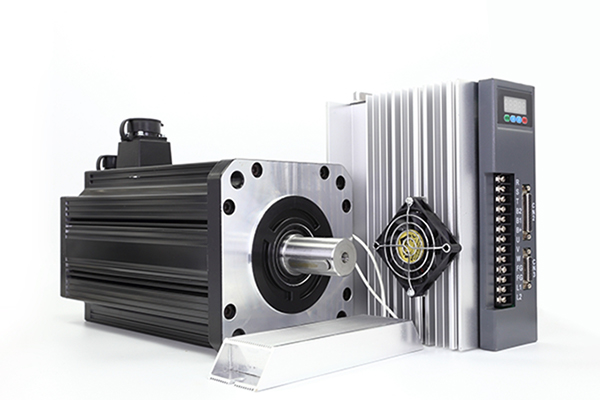
What is a Servo Motor?
 There are some special types of application of electrical motor where rotation of the motor is required for just a certain angle ...
There are some special types of application of electrical motor where rotation of the motor is required for just a certain angle ...How to Test Servo Motor?
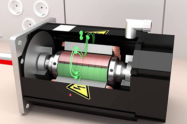 Servo motors are devices that convert electrical signals into mechanical motion and are widely used in industrial automation, ...
Servo motors are devices that convert electrical signals into mechanical motion and are widely used in industrial automation, ...How to Maintain Servo Motor?
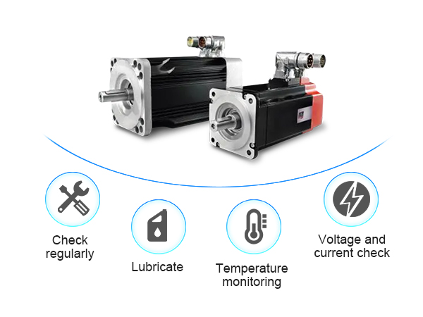 Servo motors play a crucial role in various industries, serving as precision control devices in applications ranging from ...
Servo motors play a crucial role in various industries, serving as precision control devices in applications ranging from ...How to Select the Suitable Power ...
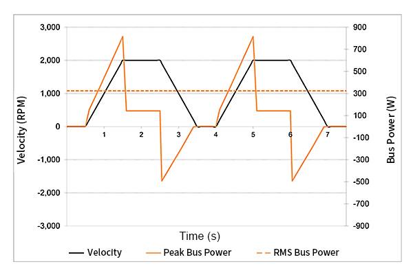 It's important to consider the unique demands of a motion control application when selecting a power supply. During ...
It's important to consider the unique demands of a motion control application when selecting a power supply. During ...What are the Types of Servo Motor?
 There are some special types of application of electrical motor where rotation of the motor is required for just a certain angle ...
There are some special types of application of electrical motor where rotation of the motor is required for just a certain angle ...