How to Calibrate Digital Servo?
Position Calibration
To verify the servo position, a marker is attached to the servo, and its orientation is measured by computer vision. A rough calibration target is used, explicitly avoiding any reliance on precise construction. Here, a simple piece of cardboard with a thin stripe is used.
The accuracy of the camera's measurements is verified by a series of physically measured positions. The deviation of these values from the camera measurement was less than the resolution of the physical measurements (1°) indicating that the visual measurement is consistent with ground truth.
Additional automated tests using the camera are then performed to verify servo position accuracy across the entire range of motion for each of the seven servos, measuring inter-servo variance. The linear least squares fit of the aggregate feedback values to visually measured positions indicates that the average uncalibrated servo has a position bias within +0.21° at the ends of its range of motion. This is less than the verified accuracy of the camera measurements and less than the servo's resolution, indicating there is no statistical nor practical basis for applying a global positional calibration.
The overall standard deviation of position feedback from the target position is 0.36°, corresponding to 1.21 units of servo resolution, and demonstrating the servo accurately reaches its target position when unloaded.

Speed Calibration
Once the servo is placed into “free spin” mode, it can produce continuous rotation, passing through the 60° dead zone. As the servo passes through this dead zone, the position feedback reports the closer of the minimum or maximum value, except in the middle of the dead zone, where it reports a not-quite-constant mid-range value.

The speed feedback continues reporting values normally until the point at which these mid-range values are returned, where it leaps between a large value in the opposite direction of motion and zero, before resuming normal operation.
Speed feedback is updated on the order of every 130 milliseconds. It is possible to poll the servo at a much higher rate and get current position data each time, but the speed register holds constant between each of the internal updates.
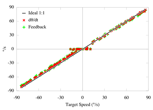
To calibrate the commanded speed and corresponding feedback to physical units, a servo is commanded to a random speed, given 0.4 seconds to accelerate, and then its average feedback and physical displacement are recorded for the following 1.5 seconds. The servo is then brought to a full stop, and the process is repeated. If the servo enters the dead zone, the sample is stopped early; if less than half of the run time has passed, the sample is discarded.
The horizontal plateau of commanded speeds with zero motion output is most likely due to static gear friction preventing any motion below a minimum torque. This indicates the servo is not performing integrative control of the speed, as it will not ramp up torque to maintain speed. This can be confirmed by manually holding the servo horn during a slow rotation, where the servo is easily immobilized and does not attempt to increase its torque.
Slow rotations are limited to very low torque, and are not reliably produced as small perturbations can halt the servo mid-rotation. Some samples are stuck at zero radians per second, and other samples can move, although both are given the same target speed.
Load Calibration
There are multiple goals for understanding how the servo measures and applies torque:
To measure and model these load-related issues, a rigid metal bar is affixed to the servo, providing attachments at known radii. The servo is clamped to a table corner, where the bar and attached masses can hang over the side.
Several motions are produced, in each case raising the bar to 45° above the horizontal and then lowering back to the table. Only data where the servo is in motion is used, so portions where the servo has not yet lifted from the table and where it is at its apex are dropped.
To verify the servo position, a marker is attached to the servo, and its orientation is measured by computer vision. A rough calibration target is used, explicitly avoiding any reliance on precise construction. Here, a simple piece of cardboard with a thin stripe is used.
The accuracy of the camera's measurements is verified by a series of physically measured positions. The deviation of these values from the camera measurement was less than the resolution of the physical measurements (1°) indicating that the visual measurement is consistent with ground truth.
Additional automated tests using the camera are then performed to verify servo position accuracy across the entire range of motion for each of the seven servos, measuring inter-servo variance. The linear least squares fit of the aggregate feedback values to visually measured positions indicates that the average uncalibrated servo has a position bias within +0.21° at the ends of its range of motion. This is less than the verified accuracy of the camera measurements and less than the servo's resolution, indicating there is no statistical nor practical basis for applying a global positional calibration.
The overall standard deviation of position feedback from the target position is 0.36°, corresponding to 1.21 units of servo resolution, and demonstrating the servo accurately reaches its target position when unloaded.
Speed Calibration
Once the servo is placed into “free spin” mode, it can produce continuous rotation, passing through the 60° dead zone. As the servo passes through this dead zone, the position feedback reports the closer of the minimum or maximum value, except in the middle of the dead zone, where it reports a not-quite-constant mid-range value.
The speed feedback continues reporting values normally until the point at which these mid-range values are returned, where it leaps between a large value in the opposite direction of motion and zero, before resuming normal operation.
Speed feedback is updated on the order of every 130 milliseconds. It is possible to poll the servo at a much higher rate and get current position data each time, but the speed register holds constant between each of the internal updates.
To calibrate the commanded speed and corresponding feedback to physical units, a servo is commanded to a random speed, given 0.4 seconds to accelerate, and then its average feedback and physical displacement are recorded for the following 1.5 seconds. The servo is then brought to a full stop, and the process is repeated. If the servo enters the dead zone, the sample is stopped early; if less than half of the run time has passed, the sample is discarded.
The horizontal plateau of commanded speeds with zero motion output is most likely due to static gear friction preventing any motion below a minimum torque. This indicates the servo is not performing integrative control of the speed, as it will not ramp up torque to maintain speed. This can be confirmed by manually holding the servo horn during a slow rotation, where the servo is easily immobilized and does not attempt to increase its torque.
Slow rotations are limited to very low torque, and are not reliably produced as small perturbations can halt the servo mid-rotation. Some samples are stuck at zero radians per second, and other samples can move, although both are given the same target speed.
Load Calibration
There are multiple goals for understanding how the servo measures and applies torque:
- Anticipate and counter positional deflection
- Map between free spin “speed" and applied torque
- Gauge external loads, e.g. objects in the gripper
To measure and model these load-related issues, a rigid metal bar is affixed to the servo, providing attachments at known radii. The servo is clamped to a table corner, where the bar and attached masses can hang over the side.
Several motions are produced, in each case raising the bar to 45° above the horizontal and then lowering back to the table. Only data where the servo is in motion is used, so portions where the servo has not yet lifted from the table and where it is at its apex are dropped.
Post a Comment:
You may also like:
Category
Featured Articles
What is a Servo Motor?
 There are some special types of application of electrical motor where rotation of the motor is required for just a certain angle ...
There are some special types of application of electrical motor where rotation of the motor is required for just a certain angle ...How to Select the Suitable Power ...
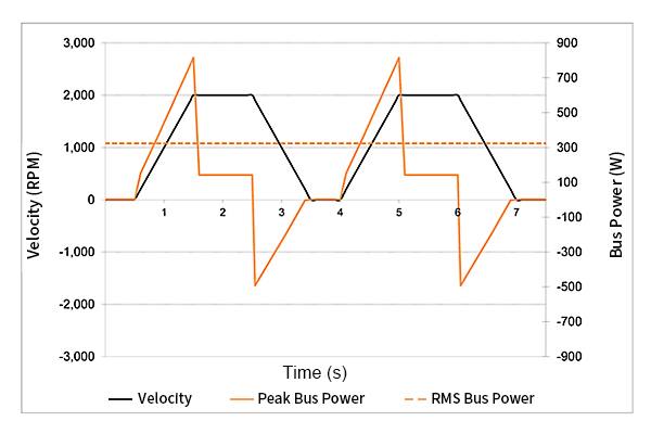 It's important to consider the unique demands of a motion control application when selecting a power supply. During ...
It's important to consider the unique demands of a motion control application when selecting a power supply. During ...What are the Types of Servo Motor?
 There are some special types of application of electrical motor where rotation of the motor is required for just a certain angle ...
There are some special types of application of electrical motor where rotation of the motor is required for just a certain angle ...How to Maintain Servo Motor?
 Servo motors play a crucial role in various industries, serving as precision control devices in applications ranging from ...
Servo motors play a crucial role in various industries, serving as precision control devices in applications ranging from ...How to Test Servo Motor?
 Servo motors are devices that convert electrical signals into mechanical motion and are widely used in industrial automation, ...
Servo motors are devices that convert electrical signals into mechanical motion and are widely used in industrial automation, ...