Research on Position Control of Servo Motor with Position Feedback
Introduction
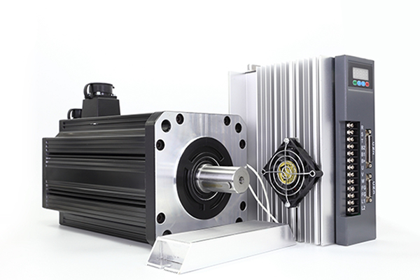
A servo motor is defined as an actuator that can be controlled precisely in terms of rotary and angular position. This type of motor is controlled with a specific angular 1 rotation with the help of an additional servomechanism. In general, this type of motor consists a simple electrical motor, attached to a servomechanism that affects the performance of the motor.
Open-loop and closed-loop DC servo motor
An open-loop DC servo motor consists of a system that has no feedback reference which can be referred to during the motor operation. Therefore, the system has no mechanism to determine errors or to verify whether the system is performing as expected. In the case of an open-loop DC servo motor, no feedback reference comes out from the servo motor which makes the servo system open-loop when connected to an external controller. However, this type of servo motor is not entirely open-loop. It has 8 an “internal feedback” mechanism that gives the position feedback to the servo controller inside the motor case.

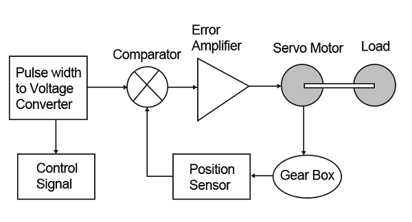
The position feedback comes from the potentiometer which is connected to the servo gear mechanism. The potentiometer reading is then converted to a voltage the values are proportional to the position of the servo shaft.
In contrast, a closed-loop DC servo motor consists of a system that operates while having a feedback mechanism for a system to verify the desired and actual condition of the output. In the case of a DC servo motor, having closed-loop feedback is a major advantage as the main controller can identify the current position of the motor as well as it can track any errors. Currently, in the market, DC servo motors come with closed-loop feedback in the form of voltage (potentiometer) or pulses (encoder).
Specifically for closed-loop voltage feedback type, the values that come from the potentiometer are located inside the servo motor case in which the voltage range is most likely to be the same as the “internal” voltage feedback.
Closed-loop DC servo motor with position feedback
The servo motors are controlled by a range of pulses namely Pulse Width Modulation (PWM). The PWM signal determines the shaft position while the pulse duration that was sent will turn the rotor to the desired position either in a clockwise counter clockwise direction. Theoretically, the servo motor expects to receive a set of pulses in every 20 milliseconds (ms) where the motor angular rotations are determined by the pulse width.

In the case of closed-loop DC servo motor, the voltage drop across the potentiometer; which is located inside the servo motor, acts as a closed-loop feedback mechanism. During the servo motor operation, the potentiometer resistance value will increase or decrease, depending on the rotation of the DC motor. By taking advantage of the properties, the resultant voltage range can be divided by the range of angular rotation to get the step voltage for each angular position. To identify the relation between voltage and angular value, a measurement was carried out by using “DAQ” to receive the voltage feedback from the servo motor. This method will be discussed further in the next topic.
Use the PI platform to control DC servo motors
There are three known methods of DC industrial servo motor position control which is by using:
A. IDE
B. Support target
C. IO package
Method A is the most common method that can be used to control the servo motor where the users use the DE software to do the coding. Next, after the program verification, the “hex” file is uploaded to the board. Conversely for Method B, a different approach is used where instead of using IDE software, the programming is performed by using software.
In addition, this method requires an installation of the support package to get the library features for software. The Simulink blocks or algorithm will then be uploaded to the board via serial transfer. The third method which is Method C works almost similarly to Method B, however, the algorithm blocks will run on the computer instead of being uploaded to the board.
Therefore, “DAQ” or “IO Card" become a medium for input or output of the system.
Similarly, this method requires an installation for the IO package, and the targeted must be uploaded with the given IDE file. All three methods have the same basic structure which includes programming, verification and communication. The programming implementations for Method A and Method B are different. However, both methods require a similar process where the verified program codes or blocks need to be uploaded on the board. For both methods, the board will immediately start to operate once the uploading process is completed. Here, it is very important to note that the parameter of the program cannot be modified since the program has already been uploaded or deployed on the board. In addition, it is possible to monitor the raw data of input and output for Method A and Method B via the “serial motor”.
However, for this study, the “serial monitor” method is not suitable for a closed-loop servomotor system which requires real-time and consistent data acquisition of the feedback. Hence for Method A and Method B, another targeted hardware is used as data acquisition hardware “DAQ” to monitor the analog feedback voltage.
On the other hand, Method C allows us to change and monitor the parameters while the program is, running. This is possible due to the developed program or algorithm only running on software. This not only provides a faster control method but also flexibility during the designing process. In addition, the communication between Simulink and board only occurs for the analog/digital input and output of the system.
Software and Hardware setup
For this study, the hardware was setup to directly control the position while tracking the actual position of the servo motor. The hardware setup consists of Mega as the 1 man controller and the power source of the servo motor. In the case of Method A and Method B, 8 another board was introduced to act as the data acquisition hardware (DAQ) to monitor the analog voltage feedback from the servo motor. The analog feedback data were then read in real-time by using the I0 package. In like manner, the actual angular position of the servo motor can be observed. Unlike those two methods, the hardware setup for Method C only requires an Mega to control and acquire feedback data from the servo motor, where it does not require any additional board.
In this study, it can be assumed that the desired angular position of all three methods came from the same source. Therefore, a similar program has been coded for each method where the desired angular position of the servo motor alternates from 0 degree to 180 degrees within 15 seconds. A simple instruction was prepared so that the data for the desired and the actual angular position of the motor could be observed.
Discussion and conclusion
In summary, the use of positional rotation servo with position, feedback is definitely important in any closed-loop electronic system. The advantages are not only that the angular position can be controlled precisely, but feedback of the actual position can also be obtained during the system operation. The voltage feedback which comes from the built-in potentiometer is accurate enough to represent the actual angular position of the motor. Moreover, introducing the position feedback features with the presented three methods will improve the control method of the servo motor from an open-loop to a closed-loop system.
A servo motor is defined as an actuator that can be controlled precisely in terms of rotary and angular position. This type of motor is controlled with a specific angular 1 rotation with the help of an additional servomechanism. In general, this type of motor consists a simple electrical motor, attached to a servomechanism that affects the performance of the motor.
Open-loop and closed-loop DC servo motor
An open-loop DC servo motor consists of a system that has no feedback reference which can be referred to during the motor operation. Therefore, the system has no mechanism to determine errors or to verify whether the system is performing as expected. In the case of an open-loop DC servo motor, no feedback reference comes out from the servo motor which makes the servo system open-loop when connected to an external controller. However, this type of servo motor is not entirely open-loop. It has 8 an “internal feedback” mechanism that gives the position feedback to the servo controller inside the motor case.
In contrast, a closed-loop DC servo motor consists of a system that operates while having a feedback mechanism for a system to verify the desired and actual condition of the output. In the case of a DC servo motor, having closed-loop feedback is a major advantage as the main controller can identify the current position of the motor as well as it can track any errors. Currently, in the market, DC servo motors come with closed-loop feedback in the form of voltage (potentiometer) or pulses (encoder).
Specifically for closed-loop voltage feedback type, the values that come from the potentiometer are located inside the servo motor case in which the voltage range is most likely to be the same as the “internal” voltage feedback.
Closed-loop DC servo motor with position feedback
The servo motors are controlled by a range of pulses namely Pulse Width Modulation (PWM). The PWM signal determines the shaft position while the pulse duration that was sent will turn the rotor to the desired position either in a clockwise counter clockwise direction. Theoretically, the servo motor expects to receive a set of pulses in every 20 milliseconds (ms) where the motor angular rotations are determined by the pulse width.
Use the PI platform to control DC servo motors
There are three known methods of DC industrial servo motor position control which is by using:
A. IDE
B. Support target
C. IO package
Method A is the most common method that can be used to control the servo motor where the users use the DE software to do the coding. Next, after the program verification, the “hex” file is uploaded to the board. Conversely for Method B, a different approach is used where instead of using IDE software, the programming is performed by using software.
In addition, this method requires an installation of the support package to get the library features for software. The Simulink blocks or algorithm will then be uploaded to the board via serial transfer. The third method which is Method C works almost similarly to Method B, however, the algorithm blocks will run on the computer instead of being uploaded to the board.
Therefore, “DAQ” or “IO Card" become a medium for input or output of the system.
Similarly, this method requires an installation for the IO package, and the targeted must be uploaded with the given IDE file. All three methods have the same basic structure which includes programming, verification and communication. The programming implementations for Method A and Method B are different. However, both methods require a similar process where the verified program codes or blocks need to be uploaded on the board. For both methods, the board will immediately start to operate once the uploading process is completed. Here, it is very important to note that the parameter of the program cannot be modified since the program has already been uploaded or deployed on the board. In addition, it is possible to monitor the raw data of input and output for Method A and Method B via the “serial motor”.
However, for this study, the “serial monitor” method is not suitable for a closed-loop servomotor system which requires real-time and consistent data acquisition of the feedback. Hence for Method A and Method B, another targeted hardware is used as data acquisition hardware “DAQ” to monitor the analog feedback voltage.
On the other hand, Method C allows us to change and monitor the parameters while the program is, running. This is possible due to the developed program or algorithm only running on software. This not only provides a faster control method but also flexibility during the designing process. In addition, the communication between Simulink and board only occurs for the analog/digital input and output of the system.
Software and Hardware setup
For this study, the hardware was setup to directly control the position while tracking the actual position of the servo motor. The hardware setup consists of Mega as the 1 man controller and the power source of the servo motor. In the case of Method A and Method B, 8 another board was introduced to act as the data acquisition hardware (DAQ) to monitor the analog voltage feedback from the servo motor. The analog feedback data were then read in real-time by using the I0 package. In like manner, the actual angular position of the servo motor can be observed. Unlike those two methods, the hardware setup for Method C only requires an Mega to control and acquire feedback data from the servo motor, where it does not require any additional board.
In this study, it can be assumed that the desired angular position of all three methods came from the same source. Therefore, a similar program has been coded for each method where the desired angular position of the servo motor alternates from 0 degree to 180 degrees within 15 seconds. A simple instruction was prepared so that the data for the desired and the actual angular position of the motor could be observed.
Discussion and conclusion
In summary, the use of positional rotation servo with position, feedback is definitely important in any closed-loop electronic system. The advantages are not only that the angular position can be controlled precisely, but feedback of the actual position can also be obtained during the system operation. The voltage feedback which comes from the built-in potentiometer is accurate enough to represent the actual angular position of the motor. Moreover, introducing the position feedback features with the presented three methods will improve the control method of the servo motor from an open-loop to a closed-loop system.
Post a Comment:
You may also like:
Category
Featured Articles
Troubleshooting of Servo Motor
 Servo motors play a crucial role in various industrial applications, providing precision control and efficient performance. ...
Servo motors play a crucial role in various industrial applications, providing precision control and efficient performance. ...Safety Precaution For Using Servo Motor
 In the realm of industrial automation, servo motors play a crucial role in achieving precision and control. These devices are ...
In the realm of industrial automation, servo motors play a crucial role in achieving precision and control. These devices are ...Why Use Servo Motor as Test Load?
 Dynamometer is mainly divided into two parts: cabinet and frame, while the frame mainly has the motor under test, torque speed ...
Dynamometer is mainly divided into two parts: cabinet and frame, while the frame mainly has the motor under test, torque speed ...Difference Between Servo and Stepper ...
 Servo motor and stepper motor are almost used in all automated industries where high precision is to be achieved. Though servo ...
Servo motor and stepper motor are almost used in all automated industries where high precision is to be achieved. Though servo ...