Commutation of Linear Servo Motors
What is commutation and how does it affect
the performance of the linear motors? Commutation is the process of switching
current in the phases in order to generate motion. Most linear motor designs
today use a three-phase brushless design. In brushed motors, commutation is
easy to understand as brushes contact a commutator and switch the current as the
motor moves. Brushless technology has no moving contacting
parts and therefore is more reliable. However, the electronics required to
control the current in the motor are a little more complex. The method of
commutation depends on the application of the motor, but it is important to
understand how the motor can be commutated and what disadvantages some methods
have.
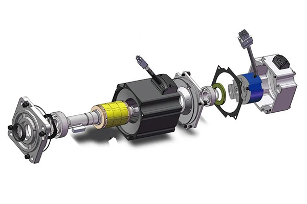
To start, let’s consider the brushed motor. When servo current is applied to the motor, the correct winding is energized by virtue of the brushes being in contact with the commutator at the point where the winding terminates. As the motor moves, the next coil in the sequence will be energized. In brushless motors, because there is no fixed reference, the first thing a control or amplifier must determine is which phase needs to be energized. There are a number of ways that this can be achieved, but by far the most popular is by using Hall effects devices. There are three of these devices, one for each phase, and they give a signal that represents the magnetic fields generated by the magnet track. By analyzing these fields, it is possible to determine which part of the magnet track the forcer is in and therefore energize the correct phase sequence.

There are three different types of commutation currently available on the market: trapezoidal, modified six step, and sinusoidal. Trapezoidal commutation is the simplest form of commutation and requires that digital Hall devices are aligned 30° electrically from the zero crossing point of the phase. At each point that a Hall signal transition takes place, the phase current sequence is changed, thus commutation of the motor occurs. This is the cheapest form of commutation and the motor phase current looks like the diagram shown above.

Modified six step commutation is very similar to trapezoidal commutation. The digital Hall devices are aligned with the zero crossing point of the phase per the diagram showing the Hall sequence of a industrial servo motor. Again, at each point that the Hall signal translation is seen the phase current is switched. However, with this method two current sensors are used and it provides a commutation sequence that is closer to the ideal sinusoidal phase current. This method is slightly more costly than trapezoidal commutation due to sensing two current levels. Both of these Hall-based methods will cause disturbance forces resulting in higher running temperature and motion that is not smooth.
The ideal means to drive any sinusoidally-wound brushless motor is by sinusoidal commutation. There are two ways that this is commonly achieved. Analog Hall effects devices can generate a sinusoidal signal as the motor passes over the magnetic poles of the magnet track. The signals, which are correct for motor commutation, are then combined with the demand signal to correctly communicate the motor.
This method is the lower cost of the two methods, but noise can be picked up on the Hall devices, affecting commutation. Another more popular method of sinusoidal commutation is by using the encoder. When a change of state is detected in the digital Hall signal, the incremental encoder signals can then be used to digitally determine where in the commutation cycle the motor is.
Commutation is done by generating a sin(θ) phase A command signal and a sin (θ + 120°) phase B command signal and multiplying this by the current command. This method of commutation gives the best results, due to the same processor being used to control current, velocity, and position, and yields faster settling time and tighter servo loops. Also, the noise on the digital Halls is much easier to filter-out, creating a more reliable system. When sinusoidal commutation is used with linear motors, the motion is smooth and the motor is driven more efficiently, causing less heating.
To start, let’s consider the brushed motor. When servo current is applied to the motor, the correct winding is energized by virtue of the brushes being in contact with the commutator at the point where the winding terminates. As the motor moves, the next coil in the sequence will be energized. In brushless motors, because there is no fixed reference, the first thing a control or amplifier must determine is which phase needs to be energized. There are a number of ways that this can be achieved, but by far the most popular is by using Hall effects devices. There are three of these devices, one for each phase, and they give a signal that represents the magnetic fields generated by the magnet track. By analyzing these fields, it is possible to determine which part of the magnet track the forcer is in and therefore energize the correct phase sequence.
There are three different types of commutation currently available on the market: trapezoidal, modified six step, and sinusoidal. Trapezoidal commutation is the simplest form of commutation and requires that digital Hall devices are aligned 30° electrically from the zero crossing point of the phase. At each point that a Hall signal transition takes place, the phase current sequence is changed, thus commutation of the motor occurs. This is the cheapest form of commutation and the motor phase current looks like the diagram shown above.
Modified six step commutation is very similar to trapezoidal commutation. The digital Hall devices are aligned with the zero crossing point of the phase per the diagram showing the Hall sequence of a industrial servo motor. Again, at each point that the Hall signal translation is seen the phase current is switched. However, with this method two current sensors are used and it provides a commutation sequence that is closer to the ideal sinusoidal phase current. This method is slightly more costly than trapezoidal commutation due to sensing two current levels. Both of these Hall-based methods will cause disturbance forces resulting in higher running temperature and motion that is not smooth.
The ideal means to drive any sinusoidally-wound brushless motor is by sinusoidal commutation. There are two ways that this is commonly achieved. Analog Hall effects devices can generate a sinusoidal signal as the motor passes over the magnetic poles of the magnet track. The signals, which are correct for motor commutation, are then combined with the demand signal to correctly communicate the motor.
This method is the lower cost of the two methods, but noise can be picked up on the Hall devices, affecting commutation. Another more popular method of sinusoidal commutation is by using the encoder. When a change of state is detected in the digital Hall signal, the incremental encoder signals can then be used to digitally determine where in the commutation cycle the motor is.
Commutation is done by generating a sin(θ) phase A command signal and a sin (θ + 120°) phase B command signal and multiplying this by the current command. This method of commutation gives the best results, due to the same processor being used to control current, velocity, and position, and yields faster settling time and tighter servo loops. Also, the noise on the digital Halls is much easier to filter-out, creating a more reliable system. When sinusoidal commutation is used with linear motors, the motion is smooth and the motor is driven more efficiently, causing less heating.
Post a Comment:
You may also like:
Category
Featured Articles
Troubleshooting of Servo Motor
 Servo motors play a crucial role in various industrial applications, providing precision control and efficient performance. ...
Servo motors play a crucial role in various industrial applications, providing precision control and efficient performance. ...Safety Precaution For Using Servo Motor
 In the realm of industrial automation, servo motors play a crucial role in achieving precision and control. These devices are ...
In the realm of industrial automation, servo motors play a crucial role in achieving precision and control. These devices are ...Why Use Servo Motor as Test Load?
 Dynamometer is mainly divided into two parts: cabinet and frame, while the frame mainly has the motor under test, torque speed ...
Dynamometer is mainly divided into two parts: cabinet and frame, while the frame mainly has the motor under test, torque speed ...Difference Between Servo and Stepper ...
 Servo motor and stepper motor are almost used in all automated industries where high precision is to be achieved. Though servo ...
Servo motor and stepper motor are almost used in all automated industries where high precision is to be achieved. Though servo ...