How to Control a Servo Motor?
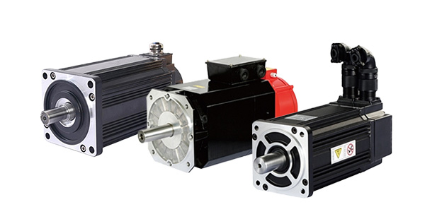
Servo Motor
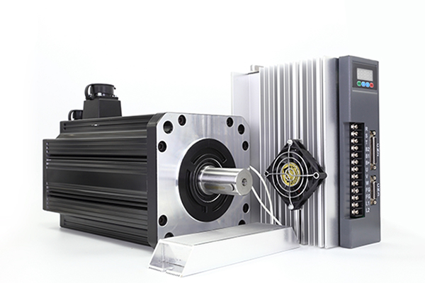
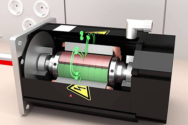
A servo is a small DC motor with the following components added: some gear reduction, a position sensor on the motor shaft, and an electronic circuit that controls the motor's operation. The gear reduction provided in a servo is large. The basic servo has a 180:1 gear ratio. This means that the DC motor shaft must make 180 revolutions to produce 1 revolution of the servo shaft. This large gear ratio reduces the speed of the servo and proportionately increases its torque.
Servo motors are typically used for angular positioning, such as in the radio control of a plane. They have a movement range of 0 up to 180 degrees, but some extend up to 210 degrees. Generally, a potentiometer measures the position of the output shaft at all times so the controller can accurately place and maintain its position.
Position Control
The external controller controls the servo system through a signal called PPM code modulation to avoid confusion with pulse width modulation. A control wire communicates the desired angular movement to the servo. The angle is determined by the duration of the pulse applied to the control wire.
PPM uses 1 to 2ms out of a 20ms time period to encode its information. The servo expects to see a pulse every 20 milliseconds (02 seconds). The length of the pulse will determine how far the motor turns. A 1.5-millisecond pulse will make the motor turn to the 90-degree position (often called the neutral position). If the pulse is shorter than 1.5ms, then the motor will turn the shaft closer to 0 degrees. If the pulse is longer than 1.5ms, the shaft turns closer to 180 degrees.

The amount of power applied to the motor is proportional to the distance it needs to travel. So, if the shaft needs to turn a large distance, the motor will run at full speed. If it needs to turn only a small amount, the motor will run at a slower speed.
Continuous Rotation Servos
A servo motor can be modified to provide continuous rotation. The process requires 2 steps:
Wiring It Up
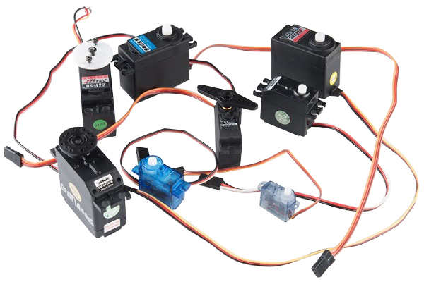
We are going to use Parallax servos mounted to a chassis with wheels so we can roll when the servos turn. Mount your controller to the BOE chassis using a tie-strap to secure it over the chassis. Be sure to place a shield between the controller and the chassis so that neither is damaged.
When powering the controller via an external power source, we should mount the battery pack on the chassis. Note that the plug mates with the power connection on the controller. To configure the controller for external power. You also need to move the jumper, moving the jumper to cover the two pins closest to the external power jack.
Use the 2 three-pin headers in the BOE-bot kit to connect the servo plugs to the board. The connections to the controller should be as indicated in diagram above. Be sure to connect the power lead to Vin (not 5V) on the controller, and connect the white lead to the controller pin issuing the PWM signals.
Torque control
Set the external output torque of the motor shaft through external analog input or direct address assignment. For example, if 10V corresponds to 5Nm, when the external analog is set to 5V, the motor shaft output is 2.5Nm. If the motor shaft load is less than 2.5Nm, the motor rotates forward; when the external load is equal to 2.5Nm, the motor does not rotate; when it is greater than 2.5Nm, the motor rotates reversely (usually occurs when there is a dynamic load). The set torque can be changed by changing the analog setting in real time, or by changing the corresponding address value through communication.
A servo is a small DC motor with the following components added: some gear reduction, a position sensor on the motor shaft, and an electronic circuit that controls the motor's operation. The gear reduction provided in a servo is large. The basic servo has a 180:1 gear ratio. This means that the DC motor shaft must make 180 revolutions to produce 1 revolution of the servo shaft. This large gear ratio reduces the speed of the servo and proportionately increases its torque.
Servo motors are typically used for angular positioning, such as in the radio control of a plane. They have a movement range of 0 up to 180 degrees, but some extend up to 210 degrees. Generally, a potentiometer measures the position of the output shaft at all times so the controller can accurately place and maintain its position.
Position Control
The external controller controls the servo system through a signal called PPM code modulation to avoid confusion with pulse width modulation. A control wire communicates the desired angular movement to the servo. The angle is determined by the duration of the pulse applied to the control wire.
PPM uses 1 to 2ms out of a 20ms time period to encode its information. The servo expects to see a pulse every 20 milliseconds (02 seconds). The length of the pulse will determine how far the motor turns. A 1.5-millisecond pulse will make the motor turn to the 90-degree position (often called the neutral position). If the pulse is shorter than 1.5ms, then the motor will turn the shaft closer to 0 degrees. If the pulse is longer than 1.5ms, the shaft turns closer to 180 degrees.
Continuous Rotation Servos
A servo motor can be modified to provide continuous rotation. The process requires 2 steps:
- Remove the mechanical stop that prevents full rotation of the output shaft.
- The second modification makes remove the potentiometer position sensor and replace with 2 resistors of equal value. The servo “think" it is in the 90-degree position.
Wiring It Up
We are going to use Parallax servos mounted to a chassis with wheels so we can roll when the servos turn. Mount your controller to the BOE chassis using a tie-strap to secure it over the chassis. Be sure to place a shield between the controller and the chassis so that neither is damaged.
When powering the controller via an external power source, we should mount the battery pack on the chassis. Note that the plug mates with the power connection on the controller. To configure the controller for external power. You also need to move the jumper, moving the jumper to cover the two pins closest to the external power jack.
Use the 2 three-pin headers in the BOE-bot kit to connect the servo plugs to the board. The connections to the controller should be as indicated in diagram above. Be sure to connect the power lead to Vin (not 5V) on the controller, and connect the white lead to the controller pin issuing the PWM signals.
Torque control
Set the external output torque of the motor shaft through external analog input or direct address assignment. For example, if 10V corresponds to 5Nm, when the external analog is set to 5V, the motor shaft output is 2.5Nm. If the motor shaft load is less than 2.5Nm, the motor rotates forward; when the external load is equal to 2.5Nm, the motor does not rotate; when it is greater than 2.5Nm, the motor rotates reversely (usually occurs when there is a dynamic load). The set torque can be changed by changing the analog setting in real time, or by changing the corresponding address value through communication.
Post a Comment:
You may also like:
Category
Featured Articles
How to Test Servo Motor?
 Servo motors are devices that convert electrical signals into mechanical motion and are widely used in industrial automation, ...
Servo motors are devices that convert electrical signals into mechanical motion and are widely used in industrial automation, ...How to Maintain Servo Motor?
 Servo motors play a crucial role in various industries, serving as precision control devices in applications ranging from ...
Servo motors play a crucial role in various industries, serving as precision control devices in applications ranging from ...What is a Servo Motor?
 There are some special types of application of electrical motor where rotation of the motor is required for just a certain angle ...
There are some special types of application of electrical motor where rotation of the motor is required for just a certain angle ...What are the Types of Servo Motor?
 There are some special types of application of electrical motor where rotation of the motor is required for just a certain angle ...
There are some special types of application of electrical motor where rotation of the motor is required for just a certain angle ...How to Select the Suitable Power ...
 It's important to consider the unique demands of a motion control application when selecting a power supply. During ...
It's important to consider the unique demands of a motion control application when selecting a power supply. During ...