Exploration of Servo Cylinder Test
This paper is intended to allow a user to fully understand the Servo Cylinder Test Sheet results, and how to apply these results to better understand your actuator. Testing on Servo Cylinder actuators is conducted in a specialized fixture, which is equipped with a load force supplying actuator, an external optical strip encoder, and a load cell. All other measurements such as encoder position and torque feedback come from the built in drive electronics. Some tests require no outside loading or measurements. These unloaded tests are conducted in a decoupled state, and do not require the fixture.
Tests procedures that are performed on a Servo Cylinder actuator can be divided into two groups, tests that can be run with only the on board drive electronics, and tests that require external loads and measurements, which are supplied by a custom test fixture. These industrial servo tests are respectively referred to as unloaded and loaded tests, and on an actuator's test sheet.
Unit Conversions
Encoder counts are directly related to motor revolutions, with one motor revolution being equivalent to 1024 encoder counts. Motor revolutions, in turn, are directly related to actuator extension by the screw lead. Actuator displacement can therefore be calculated in terms of encoder counts by the equation below.
Actuator Displacement = Encoder Counts*(srew lead/1024)
Using this equation an actuator with a 0.125" lead would show 0.125" of displacement for a commanded motion of 1024 counts. Torque Feedback is used throughout the Test Sheet to define the Servo Cylinder's torque measurement. In the Servo Cylinder manual, this is sometimes referred to as Servo Motor Current. This measurement can be used as an approximation of motor current through the following relationship:
The approximate force output of the actuator can be calculated using the force constant and offset determined in the Force Constant Analysis.
Motor Constant Analysis
The actuator's motor constant is measured by commanding the actuator to run at its maximum possible torque/speed while moving in two positions and recording position, time, and supply voltage, in a completely unloaded state. This data is processed to reveal the motor constant Kv = steady state speed (rpm) or steady state supply voltage (volts). We also calculate the actuator constant as Kva = steady state speed (in/s) or steady state supply voltage (volts). The calculated motor constant and actuator constant can be found in the data table, is 200.1 (rpm/volt), which is typical. Note that this test and all other tests are conducted using a 36V power supply.

Running Friction Analysis
During the running friction test, the actuator is given trapezoidal trajectory commands to slowly extend and retract in two positions. The actuator speed is set to 50,000, and the actuator is configured to stream position and the servo motor torque required to maintain the constant speed trajectory. For constant-speed motions, torque feedback (sometimes referred to as Motor Current/Streaming Variable 3) defines the torque required to overcome resistance to the defined motion. In an unloaded state, at a low speed, external forces and internal viscous forces are eliminated, enabling us to use the torque feedback measurement as a measurement of the internal friction of the actuator, as well as the base level of torque required to move the actuator.
Torque feedback uses the same units as the actuator max torque setting. Most actuators require an average of 1,000 torque counts to overcome internal frictions. The data collected in this test is closely related to the back drive force test, which is an external measurement of the force required to extend the actuator at low speed.
Viscous Friction Analysis
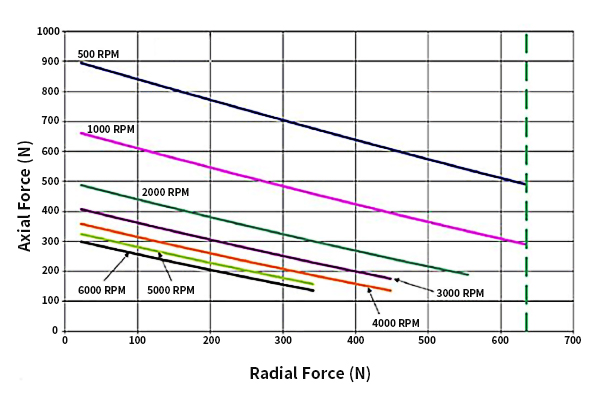
The viscous friction analysis is conducted by commanding trajectory moves with different speed settings, while recording position, time, and torque feedback. Data from the steady-state portions of these movements is processed to give steady-state average torque output, which is plotted against steady-state speed in inches of actuator extension per second. The linear trend observed in the viscosity test plot, allows us to calculate the average servo torque required to operate the actuator at any running speed.

Viscosity Test Data Explanation
The actuator viscosity constant is measured in terms of internal torque feedback per running speed in inches per second and is calculated based on several running speed data points. This data can be used to anticipate the affect that running speed will have on force output.
On this actuator, as running speed approaches 10in/s running friction is nearly doubled over the low-speed running friction observed in the running friction test. These results can also be used to estimate the physical speed of the actuator based on the trajectory speed setting, by matching the speed setting in the legend to the running speed indicated by each data point. Actuator viscosity is caused largely by viscous effects within the motor windings (iron losses), and viscous effects of the grease lubrication. If the viscous constant is very high, this can be an indication that the motor has been damaged.
Tests procedures that are performed on a Servo Cylinder actuator can be divided into two groups, tests that can be run with only the on board drive electronics, and tests that require external loads and measurements, which are supplied by a custom test fixture. These industrial servo tests are respectively referred to as unloaded and loaded tests, and on an actuator's test sheet.
Unit Conversions
Encoder counts are directly related to motor revolutions, with one motor revolution being equivalent to 1024 encoder counts. Motor revolutions, in turn, are directly related to actuator extension by the screw lead. Actuator displacement can therefore be calculated in terms of encoder counts by the equation below.
Actuator Displacement = Encoder Counts*(srew lead/1024)
Using this equation an actuator with a 0.125" lead would show 0.125" of displacement for a commanded motion of 1024 counts. Torque Feedback is used throughout the Test Sheet to define the Servo Cylinder's torque measurement. In the Servo Cylinder manual, this is sometimes referred to as Servo Motor Current. This measurement can be used as an approximation of motor current through the following relationship:
Phase Currentpeak(amps)=0.000763*Torque Feedback
The approximate force output of the actuator can be calculated using the force constant and offset determined in the Force Constant Analysis.
Motor Constant Analysis
The actuator's motor constant is measured by commanding the actuator to run at its maximum possible torque/speed while moving in two positions and recording position, time, and supply voltage, in a completely unloaded state. This data is processed to reveal the motor constant Kv = steady state speed (rpm) or steady state supply voltage (volts). We also calculate the actuator constant as Kva = steady state speed (in/s) or steady state supply voltage (volts). The calculated motor constant and actuator constant can be found in the data table, is 200.1 (rpm/volt), which is typical. Note that this test and all other tests are conducted using a 36V power supply.
Running Friction Analysis
During the running friction test, the actuator is given trapezoidal trajectory commands to slowly extend and retract in two positions. The actuator speed is set to 50,000, and the actuator is configured to stream position and the servo motor torque required to maintain the constant speed trajectory. For constant-speed motions, torque feedback (sometimes referred to as Motor Current/Streaming Variable 3) defines the torque required to overcome resistance to the defined motion. In an unloaded state, at a low speed, external forces and internal viscous forces are eliminated, enabling us to use the torque feedback measurement as a measurement of the internal friction of the actuator, as well as the base level of torque required to move the actuator.
Torque feedback uses the same units as the actuator max torque setting. Most actuators require an average of 1,000 torque counts to overcome internal frictions. The data collected in this test is closely related to the back drive force test, which is an external measurement of the force required to extend the actuator at low speed.
Viscous Friction Analysis
The viscous friction analysis is conducted by commanding trajectory moves with different speed settings, while recording position, time, and torque feedback. Data from the steady-state portions of these movements is processed to give steady-state average torque output, which is plotted against steady-state speed in inches of actuator extension per second. The linear trend observed in the viscosity test plot, allows us to calculate the average servo torque required to operate the actuator at any running speed.
Viscosity Test Data Explanation
The actuator viscosity constant is measured in terms of internal torque feedback per running speed in inches per second and is calculated based on several running speed data points. This data can be used to anticipate the affect that running speed will have on force output.
On this actuator, as running speed approaches 10in/s running friction is nearly doubled over the low-speed running friction observed in the running friction test. These results can also be used to estimate the physical speed of the actuator based on the trajectory speed setting, by matching the speed setting in the legend to the running speed indicated by each data point. Actuator viscosity is caused largely by viscous effects within the motor windings (iron losses), and viscous effects of the grease lubrication. If the viscous constant is very high, this can be an indication that the motor has been damaged.
Post a Comment:
You may also like:
Category
Featured Articles
Troubleshooting of Servo Motor
 Servo motors play a crucial role in various industrial applications, providing precision control and efficient performance. ...
Servo motors play a crucial role in various industrial applications, providing precision control and efficient performance. ...Safety Precaution For Using Servo Motor
 In the realm of industrial automation, servo motors play a crucial role in achieving precision and control. These devices are ...
In the realm of industrial automation, servo motors play a crucial role in achieving precision and control. These devices are ...Why Use Servo Motor as Test Load?
 Dynamometer is mainly divided into two parts: cabinet and frame, while the frame mainly has the motor under test, torque speed ...
Dynamometer is mainly divided into two parts: cabinet and frame, while the frame mainly has the motor under test, torque speed ...Difference Between Servo and Stepper ...
 Servo motor and stepper motor are almost used in all automated industries where high precision is to be achieved. Though servo ...
Servo motor and stepper motor are almost used in all automated industries where high precision is to be achieved. Though servo ...