The Design of DC Servo Motor Controller System Based on a DSP Controller
Introduction
In many automatic control systems, especially in fields such as medical treatment and robots, precise control of parameters like position, speed, torque and high reliability are required. Due to its characteristics of smooth speed regulation and easy control, DC Motor speed control systems are widely used in automation equipment and production departments which have high requirement on control such as CNC machine tools and industrial robots. The trend of the development of the servo motor control area is the embedded control system with DSP as its core controller for its great function of input and output (I/O) and capability of high speed digital signal processing. So it is meaningful and promising to develop a servo control system of DC motor with high performance and reliability.
This paper developed a DC servo motor control system based on a DSP controller after analyzing the control demand of the robot in our lab and taking the experience of other researchers domestic and abroad. The system consisted of the driver and controller for the DC servo motor. The experimental results showed that the system could run with high precision and reliability in either speed mode or position mode and could keep parameters like PID parameters saved despite the loss of power.
Hardware Structure
The entire DC servo motor control system includes the host computer, motor driving part, parameter storage, and signal sampling and processing part. The structure diagram of the system is illustrated in the following picture. The function of the host computer is sending instructions via RS485 bus to the controller in order to modify the parameters or run the motor; The core part of the controller is the minimum system based on a DSP chip, which is specially developed by TI company for the application of motor; The DC servo motor driving part is a H-bridge driving circuit made up of a driving chip and four power; a photoelectric encoder is used as the signal sampling unit which measures the speed of the motor; A data memory chip is utilized to save parameters like speed, position, accelerator and PID parameters.
DSP minimum system and peripheral circuits. The hardware circuits are important parts of the system, based on which the software system can run normally to fulfill the control task. This part presents the circuit design of the functional modules. As is shown in the following picture, the hardware of the system is made up of the following parts: DSP minimum system, motor driving unit, storage unit, and upper host computer, and the main parts are the DSP minimum system and industrial DC servo motor driving unit.

The DSP minimum system is the core of the
control system, which generates control signals calculated according to the
feedback signal and control algorithm. The industrial DC servo circuit of the minimum system
includes a power supply unit, timer unit, SRAM, and JTAG interface. The
peripheral circuits compromise a storage unit and a communication interface
unit. A nonvolatile ferro-electric memory (FM24CL32) is used to store the
parameters that the system needs to run correctly.
The RS485 bus is one of the widely used
buses in industrial sites for its mature technology and easy manipulation. So
the RS485 bus is used in this system to communicate with the host PC. At the
same time, the circuit of the CAN bus is reserved as another way to
communicate. Motor driving circuit. The motor driving
circuit is one of the most important circuits in the system, which directly
determines the performance of the motor.
Software Design
A well-performed control system has not
only reliable hardware but efficient and useful software as well. The following picture
illustrates the closed-loop control diagram of the system. The system includes
a speed loop and a position loop. The calculated position result is firstly
converted to speed and finally changed into voltage loaded on the motor.


Post a Comment:
You may also like:
 There are some special types of application of electrical motor where rotation of the motor is required for just a certain angle ...
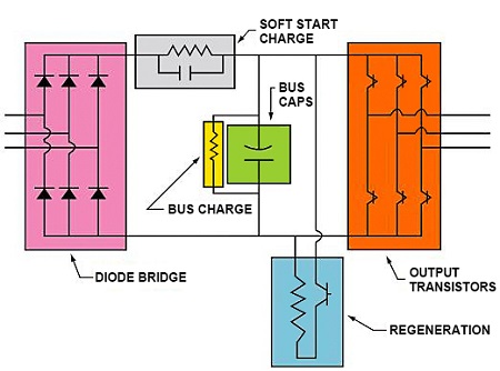 Servo motors come in so many types and flavors that it is difficult to define them in a way that is accurate and universally ...
 Dynamometer is mainly divided into two parts: cabinet and frame, while the frame mainly has the motor under test, torque speed ...
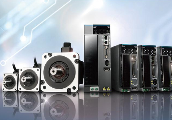 Servo system is a commonly used control system, widely used in industrial automation. It compares the output signal with the ...
 In the ever-evolving landscape of the food industry, technological advancements play a pivotal role in enhancing efficiency, ...