Servo System for Tracking Radar Antenna
Introduction
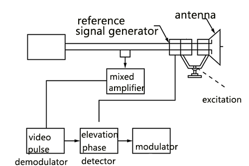
The Antiaircraft Fire-Control System employs electrical servos for driving the tracking-radar antenna in azimuth and elevation while tracking a target. A functional block diagram showing the interconnection of the units is drawn in the following picture. Only the elevation control channel is illustrated since both channels are identical except that the azimuth power servo amplifier drives four motors. In contrast, the elevation servo amplifier drives a single motor. The units shown are those used in the automatic-tracking mode.
Purpose
The primary purpose of the azimuth and elevation servos is to steer the tracking radar antenna so that an airborne target may be tracked automatically in two CO coordinates as it moves through space. Another purpose of the servos is to provide for rapid slewing of the tracking antenna to the angular position of the associated acquisition-radar antenna and also provide alignment (in elevation) of the optical system with the tracking radar and antenna. The two servos also supply angular-position data to a computer and remote indicators.
Operation
An 1800-rpm conical-scan drive motor attached to an off-axis antenna feed spins the beam in space and, places 30-cps amplitude modulation on the chain of echo signals received from a target. After amplification and detection by the radar receiver, the 30-cps amplitude-modulated video echo pulses are applied to a pulse modulator where the modulation signal is recovered from the video pulses. The 30-cps signal is then applied to an elevation angle phase-sensitive detector together with a 30-cps signal from a reference-signal generator coupled to the conical-scan drive motor at the antenna.
The reference signal serves as a phase reference for the elevation angle of the antenna-beam axis servo measured concerning the parabolic-reflector axis. If the antenna is on target, no error signal is generated in the phase-sensitive detector. If the antenna is off target in elevation, there is an error signal whose magnitude is a measure of the amount the antenna's a-beam axis is off target and whose polarity concerning the elevation reference signal depends upon whether the beam axis is above or below the target. Hence, as the antenna tracks a moving target, the output of the phase-sensitive detector is slowly varying positive or negative voltage, the magnitude and polarity of which are a measure of the elevation tracking error.
The error signal from the phase-sensitive detector modulates a 400-cps carrier voltage, and the modulated carrier is then amplified in a low-power electronic servo amplifier. This amplifier consists of two stages of voltage amplification, a phase inverter, and a push-pull output stage. The phase inverter provides two signals, 180" out of phase, for driving the push-pull output stage.
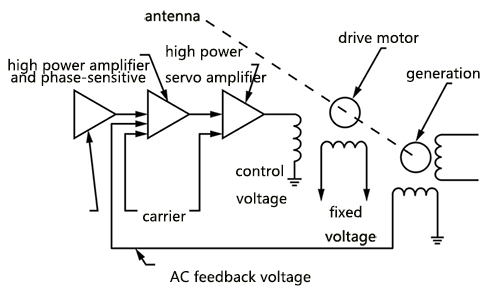
The output of the low-power servo amplifier is then applied to the input of a 400-cps high-power servo pre-amplifier. Also applied to the pre-amplifier input is a 400-cps feedback voltage from an AC tachometer generator that is coupled to the elevation drive shaft of the antenna. An AC velocity feedback voltage is thus provided in the servo system. Because the high-power servo amplifier stage requires a push-pull d-c voltage input signal, the pre-amplifier also includes a modulator. The input signal to the pre-amplifier is, therefore, a modulated 400-cps carrier signal and the output is the modulation envelope.
H1(s) = transfer function of techometer generator
e = actuating signal of servo system
r = line of sight elevation angle
c = antenna elevation angle
Noise
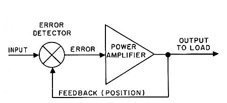
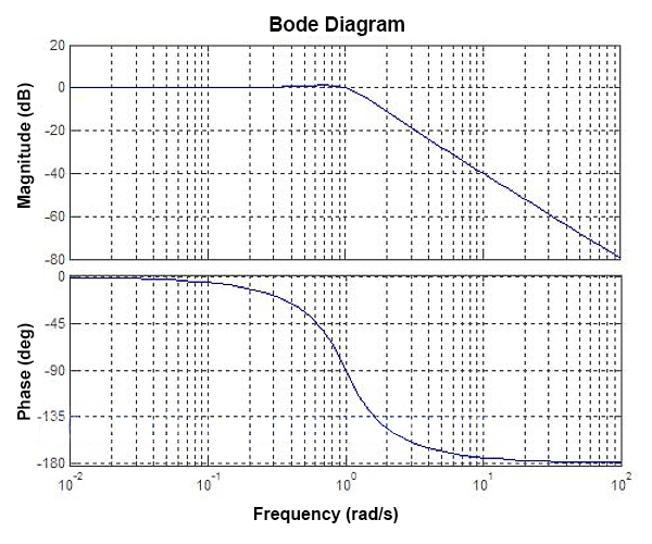
The presence of radar noise in the line-of-sight signal prevents the actuating signal e from being a true measure of the system error, ye = r-c. To minimize the effect of noise, the bandwidth of the system has been kept at a low value so that the servo mechanism acts as a low-pass filter.
The Antiaircraft Fire-Control System employs electrical servos for driving the tracking-radar antenna in azimuth and elevation while tracking a target. A functional block diagram showing the interconnection of the units is drawn in the following picture. Only the elevation control channel is illustrated since both channels are identical except that the azimuth power servo amplifier drives four motors. In contrast, the elevation servo amplifier drives a single motor. The units shown are those used in the automatic-tracking mode.
Purpose
The primary purpose of the azimuth and elevation servos is to steer the tracking radar antenna so that an airborne target may be tracked automatically in two CO coordinates as it moves through space. Another purpose of the servos is to provide for rapid slewing of the tracking antenna to the angular position of the associated acquisition-radar antenna and also provide alignment (in elevation) of the optical system with the tracking radar and antenna. The two servos also supply angular-position data to a computer and remote indicators.
Operation
An 1800-rpm conical-scan drive motor attached to an off-axis antenna feed spins the beam in space and, places 30-cps amplitude modulation on the chain of echo signals received from a target. After amplification and detection by the radar receiver, the 30-cps amplitude-modulated video echo pulses are applied to a pulse modulator where the modulation signal is recovered from the video pulses. The 30-cps signal is then applied to an elevation angle phase-sensitive detector together with a 30-cps signal from a reference-signal generator coupled to the conical-scan drive motor at the antenna.
The reference signal serves as a phase reference for the elevation angle of the antenna-beam axis servo measured concerning the parabolic-reflector axis. If the antenna is on target, no error signal is generated in the phase-sensitive detector. If the antenna is off target in elevation, there is an error signal whose magnitude is a measure of the amount the antenna's a-beam axis is off target and whose polarity concerning the elevation reference signal depends upon whether the beam axis is above or below the target. Hence, as the antenna tracks a moving target, the output of the phase-sensitive detector is slowly varying positive or negative voltage, the magnitude and polarity of which are a measure of the elevation tracking error.
The error signal from the phase-sensitive detector modulates a 400-cps carrier voltage, and the modulated carrier is then amplified in a low-power electronic servo amplifier. This amplifier consists of two stages of voltage amplification, a phase inverter, and a push-pull output stage. The phase inverter provides two signals, 180" out of phase, for driving the push-pull output stage.
The output of the low-power servo amplifier is then applied to the input of a 400-cps high-power servo pre-amplifier. Also applied to the pre-amplifier input is a 400-cps feedback voltage from an AC tachometer generator that is coupled to the elevation drive shaft of the antenna. An AC velocity feedback voltage is thus provided in the servo system. Because the high-power servo amplifier stage requires a push-pull d-c voltage input signal, the pre-amplifier also includes a modulator. The input signal to the pre-amplifier is, therefore, a modulated 400-cps carrier signal and the output is the modulation envelope.
H1(s) = transfer function of techometer generator
e = actuating signal of servo system
r = line of sight elevation angle
c = antenna elevation angle
The presence of radar noise in the line-of-sight signal prevents the actuating signal e from being a true measure of the system error, ye = r-c. To minimize the effect of noise, the bandwidth of the system has been kept at a low value so that the servo mechanism acts as a low-pass filter.
Post a Comment:
You may also like:
Category
Featured Articles
What are the Basic Components of ...
 Servomechanisms, called servos for short, are the basic building blocks of power drives. In this manual what we mean by a power ...
Servomechanisms, called servos for short, are the basic building blocks of power drives. In this manual what we mean by a power ...What is the Bandwidth of ...
 For a servo system, the bandwidth is the maximum sine wave frequency to which the servo system can respond. In professional ...
For a servo system, the bandwidth is the maximum sine wave frequency to which the servo system can respond. In professional ...What Should Consider Before Using ...
 Servo system is a commonly used control system, widely used in industrial automation. It compares the output signal with the ...
Servo system is a commonly used control system, widely used in industrial automation. It compares the output signal with the ...What is Servo System?
 A feedback control system used to precisely follow or reproduce a process. Also known as a follower system. In many cases, a ...
A feedback control system used to precisely follow or reproduce a process. Also known as a follower system. In many cases, a ...