Servo Motors Classification Based on the Accelerating Factor
|
Nomenclature |
|
|
TM |
motor torque |
|
JM |
motor momentum of inertia |
|
TM,rms |
motor root mean square torque |
|
TM,N |
motor nominal torque |
|
TM,max |
servo-motor maximum torque |
|
ωM |
motor angular speed |
|
ωM,N |
motor nominal angular speed |
|
PN |
motor nominal power |
|
m |
motor mass |
|
VN |
motor nominal voltage |
|
p |
motor poles |
|
TL |
load torque |
|
JL |
load momentum of inertia |
|
ωL |
load angular speed |
|
τ |
transmission ratio |
|
η |
transmission mechanical efficiency |
|
α |
accelerating factor |
|
β |
load factor |
|
ta |
cycle time |
|
Cth |
motor thermal capacity |
|
Rth |
motor thermal resistance |
|
τth |
motor thermal constant |
|
ωM,max |
maximum speed achievable by the motor |
|
ωL,max |
maximum speed achieved by the load |
|
KT |
torque constant |
|
i |
current flowing in motor windings |
This work is focused on the analysis of the so-called accelerating factor (α) defined, for each motor, as the ratio between the square of the motor nominal torque and its momentum of inertia.
1.Introduction
The need to increase production capability, while maintaining the quality standards, requires the implementation of automatic machines performance ever higher. In this context, it is of strategic importance in the machine design phase the correct selection of the motor reducer unit. Unfortunately, the choice of the electric motor required to handle a dynamic load, is closely related to the transmission choice. This operation, in fact, is bound by the limitations imposed by the motor working range and it is subjected to a great number of constraints that depend indirectly on the motor (through its inertia) and on the reducer, whose selection is the object of the design. This work is focused on the analysis of the "continuous duty power rate" also called "accelerating factor" defined, for each motor, as the ratio between the square of the motor nominal torque and its momentum of inertia. Each manufacturer of brushless synchronous motors adopts its own technological solutions and its constructive layout, which is generally different from those of another producer. However, the designer of an automatic machine who has to choose a motor, can consider all the motors as black boxes characterized by their "accelerating factor". Actually there is not any theoretical study that investigates the dependence of the accelerating factor on the electro-mechanical characteristics of the motor, therefore the comparison of motor performances in terms of their accelerating factor is possible only in relative terms and not in absolute. The aim of this paper is to put the groundwork for a deeper analysis of the accelerating factor, in order to give to the designer of an automatic machine a tool to critically evaluate the performance of motors, not only as compared to the other available, but also in absolute terms.
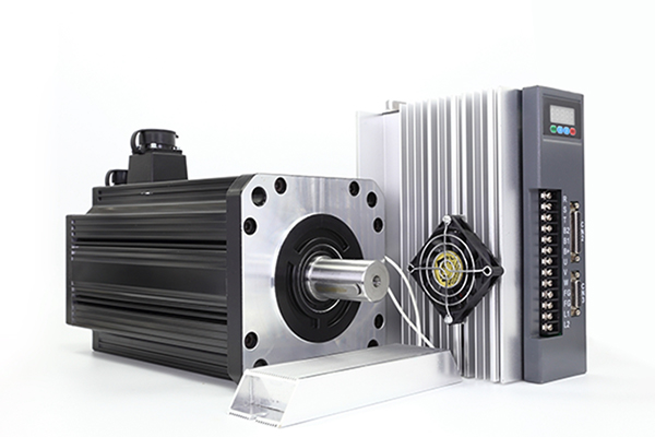
2.The Motor
Brushless motors are the most widespread electrical actuators in automation field, which working range could be approximately subdivided into a continuous working zone (called S1, bound by motor rated torque) and in a dynamic one (called S6, bound by the maximum motor torque TM,max). Usually the motor rated torque decreases with the motor speed ωM. To simplify the rated torque trend and to have a cautionary approach, the continuous working range is approximated to a rectangle, identifying two values TM,N and ωM,max.
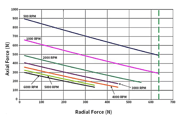
Note how the approximation used to make the S1 field rectangular, actually has consequences on the value of TM,N and ωM,max. Information on catalogues are often poor and, in the best case, when speed/curve torque is available, they should be managed to obtain the interesting parameters. Note how the maximum torque achieved by the servo-motor TM,max strongly depends on the drive associated with it and it is generally different from the motor theoretical maximum torque. At low speed, the constraint introduced by the drive systems is related to the maximum current supplied to the motor. Since torque depends on the current, this limit translates into a horizontal line on the motor working field corresponding to a maximum torque different from the theoretical one. At higher speed, this constraint is overcome by the condition on the maximum voltage endurable, which causes a reduction of the motor maximum torque with its speed.

3.The Thermal Problem of Electrical Motors
The thermal problem is of great importance in electric motors, and is generally the most binding condition in the choice of an electric motor for industrial applications. During their operation, in fact, motors waste power Wd as heat: this is primarily because the windings are affected by the current flow (copper losses), but also for the eddy currents (iron losses) and mechanical effects. The power lost as heat determines an increase in temperature of the motor. Heat is partially removed from the environment at least until a stationary condition is determined. Naming θ(t) the difference of temperature at time t between motor and environment, Cth the motor thermal capacity and Rth its thermal resistance.
 Figure depicts the trends of motor weight (M) and nominal torques (TM,N) for the considered motors ordered with increasing momentum of inertia JM.

Looking the charts some interesting consideration can be done:
1.Introduction
The need to increase production capability, while maintaining the quality standards, requires the implementation of automatic machines performance ever higher. In this context, it is of strategic importance in the machine design phase the correct selection of the motor reducer unit. Unfortunately, the choice of the electric motor required to handle a dynamic load, is closely related to the transmission choice. This operation, in fact, is bound by the limitations imposed by the motor working range and it is subjected to a great number of constraints that depend indirectly on the motor (through its inertia) and on the reducer, whose selection is the object of the design. This work is focused on the analysis of the "continuous duty power rate" also called "accelerating factor" defined, for each motor, as the ratio between the square of the motor nominal torque and its momentum of inertia. Each manufacturer of brushless synchronous motors adopts its own technological solutions and its constructive layout, which is generally different from those of another producer. However, the designer of an automatic machine who has to choose a motor, can consider all the motors as black boxes characterized by their "accelerating factor". Actually there is not any theoretical study that investigates the dependence of the accelerating factor on the electro-mechanical characteristics of the motor, therefore the comparison of motor performances in terms of their accelerating factor is possible only in relative terms and not in absolute. The aim of this paper is to put the groundwork for a deeper analysis of the accelerating factor, in order to give to the designer of an automatic machine a tool to critically evaluate the performance of motors, not only as compared to the other available, but also in absolute terms.
2.The Motor
Brushless motors are the most widespread electrical actuators in automation field, which working range could be approximately subdivided into a continuous working zone (called S1, bound by motor rated torque) and in a dynamic one (called S6, bound by the maximum motor torque TM,max). Usually the motor rated torque decreases with the motor speed ωM. To simplify the rated torque trend and to have a cautionary approach, the continuous working range is approximated to a rectangle, identifying two values TM,N and ωM,max.
Note how the approximation used to make the S1 field rectangular, actually has consequences on the value of TM,N and ωM,max. Information on catalogues are often poor and, in the best case, when speed/curve torque is available, they should be managed to obtain the interesting parameters. Note how the maximum torque achieved by the servo-motor TM,max strongly depends on the drive associated with it and it is generally different from the motor theoretical maximum torque. At low speed, the constraint introduced by the drive systems is related to the maximum current supplied to the motor. Since torque depends on the current, this limit translates into a horizontal line on the motor working field corresponding to a maximum torque different from the theoretical one. At higher speed, this constraint is overcome by the condition on the maximum voltage endurable, which causes a reduction of the motor maximum torque with its speed.
3.The Thermal Problem of Electrical Motors
The thermal problem is of great importance in electric motors, and is generally the most binding condition in the choice of an electric motor for industrial applications. During their operation, in fact, motors waste power Wd as heat: this is primarily because the windings are affected by the current flow (copper losses), but also for the eddy currents (iron losses) and mechanical effects. The power lost as heat determines an increase in temperature of the motor. Heat is partially removed from the environment at least until a stationary condition is determined. Naming θ(t) the difference of temperature at time t between motor and environment, Cth the motor thermal capacity and Rth its thermal resistance.
The differential equation for the equilibrium of power is: Cth*dθ/dt+θ/Rth=Wd
that can be rewritten as: τth*dθ/dt+θ=WdRth
where: τth=RthCth
4.Servo Motor Comparison
The aim of this work is to put the basis of a detailed analysis of the accelerating factor (or continuous duty power rate). The starting point is the answer to the question: "Let's assume that motors with different sizes are hard to be compared, may similar motors have accelerating factors α extremely different?" A negative answer to this question would make unnecessary any subsequent consideration, indicating that manufacturing parameters marginally influence the accelerating factor. That means the commercial brushless motors currently on the market have similar electromechanical features, presumably best suited to obtaining high values of α. On the opposite, a positive answer would open a research field to find which are the electromechanical features of a motor that most influence the accelerating factor and which is (if it exists) the theoretical or technological value of α whose overtaking is impossible or technically not convenient. A way to answer the question is to collect enough information from different manufacturers catalogues for a significant number of motors. The resulting database will be a useful instrument to compare different commercial devices and a suitable tool to highlight how the accelerating factor can't be the only parameter to describe the performance of a motor and how all motors features influence the design of a machine.
4.1 The Database
The database collects the main information available on catalogues of about 300 motors whose power is between 15W and 15kW. Information collected relate to: brand, model, type of motor (AC or DC), torque coefficient, winding electrical resistance, number of poles, geometrical dimensions and, naturally, motor nominal torque and the rotor momentum of inertia. The momentum of inertia JM includes the inertia of the rotor and the one of the positioning sensor, a needed component for the machine functioning and thus a part of it. The inertia of any brake systems, or related to any additional sensors is neglected.
4.2 Data Analysis
Figure represents the trend of the accelerating factor (y axis) for the entire population of considered motors (x axis). Motors are identified by a unique growing index. Notice how α can assume values really different, and how some motors have an accelerating factor extremely high compared to the considered population.
 The graph can not highlights if this high values of the accelerating factor are due to a high nominal torque, or to small rotor inertia, or to the combination of the two factors. It is also unclear whether the accelerating factor is related to the motor size or not. For this reason, values of α, motor nominal torque TM,N and motor momentum of inertia JM are reported on the same chart for all the motors in the database. For ease of consultation, motors are ordered with increasing momentum of inertia. The three series of data are normalized on their respective maximum value to allow a comparison between series.
The aim of this work is to put the basis of a detailed analysis of the accelerating factor (or continuous duty power rate). The starting point is the answer to the question: "Let's assume that motors with different sizes are hard to be compared, may similar motors have accelerating factors α extremely different?" A negative answer to this question would make unnecessary any subsequent consideration, indicating that manufacturing parameters marginally influence the accelerating factor. That means the commercial brushless motors currently on the market have similar electromechanical features, presumably best suited to obtaining high values of α. On the opposite, a positive answer would open a research field to find which are the electromechanical features of a motor that most influence the accelerating factor and which is (if it exists) the theoretical or technological value of α whose overtaking is impossible or technically not convenient. A way to answer the question is to collect enough information from different manufacturers catalogues for a significant number of motors. The resulting database will be a useful instrument to compare different commercial devices and a suitable tool to highlight how the accelerating factor can't be the only parameter to describe the performance of a motor and how all motors features influence the design of a machine.
4.1 The Database
The database collects the main information available on catalogues of about 300 motors whose power is between 15W and 15kW. Information collected relate to: brand, model, type of motor (AC or DC), torque coefficient, winding electrical resistance, number of poles, geometrical dimensions and, naturally, motor nominal torque and the rotor momentum of inertia. The momentum of inertia JM includes the inertia of the rotor and the one of the positioning sensor, a needed component for the machine functioning and thus a part of it. The inertia of any brake systems, or related to any additional sensors is neglected.
4.2 Data Analysis
Figure represents the trend of the accelerating factor (y axis) for the entire population of considered motors (x axis). Motors are identified by a unique growing index. Notice how α can assume values really different, and how some motors have an accelerating factor extremely high compared to the considered population.
- High values of accelerating factor can be obtained, because of increased motor nominal torque
- Motor nominal torques and rotor inertia seem to be proportional each others
- Motors with same momentum of inertia can have accelerating factors extremely different
- Motors momentum of inertia and mass seem to be proportional
These considerations give a first answer to the question done: commercial brushless motors are built with different designs and generally have different performances. It means that some motors are better than others. Actually, this conclusion is the starting point to investigate what are the electromechanical characteristics that allow a motor to be more performing. Let's now consider the transmission that could be coupled with each motor, such that condition on thermal problem is verified. The range of suitable transmission ratios can be calculated by solving equation.
5.Conclusions
The "accelerating factor", or "continuous duty power rate", it is a parameter characterizing the performance of a motor and it is defined as the ratio between the motor rated torque and the square of its rotor momentum of inertia. The higher is the accelerating factor α, the wider is the range of transmission ratios that can be used for coupling the motor to the load to be moved. The designer who is choosing the motor reducer unit, however, has difficulties in understanding whether the choice done is the best or not, because there are no absolute references on the accelerating factor on which perform the selection. In other words, it is impossible, at now, to evaluate if the chosen motor is the best solution for an application, or if a smaller one with the same accelerating factor, and therefore better for weight and dimensions, is available in commerce. The analysis reveals how motors for automation field (taking into account only synchronous brushless motors) are extremely heterogeneous in terms of performance and highlights the needing to define benchmarks for the accelerating factor to help the designer in selecting the best motor transmission coupling.
Post a Comment:
You may also like:
Category
Featured Articles
Difference Between Servo and Stepper ...
 Servo motor and stepper motor are almost used in all automated industries where high precision is to be achieved. Though servo ...
Servo motor and stepper motor are almost used in all automated industries where high precision is to be achieved. Though servo ...Why Use Servo Motor as Test Load?
 Dynamometer is mainly divided into two parts: cabinet and frame, while the frame mainly has the motor under test, torque speed ...
Dynamometer is mainly divided into two parts: cabinet and frame, while the frame mainly has the motor under test, torque speed ...Safety Precaution For Using Servo Motor
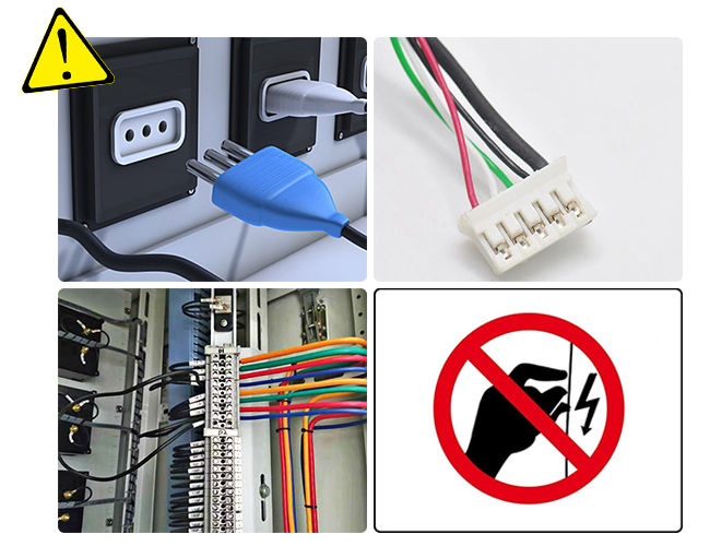 In the realm of industrial automation, servo motors play a crucial role in achieving precision and control. These devices are ...
In the realm of industrial automation, servo motors play a crucial role in achieving precision and control. These devices are ...Troubleshooting of Servo Motor
 Servo motors play a crucial role in various industrial applications, providing precision control and efficient performance. ...
Servo motors play a crucial role in various industrial applications, providing precision control and efficient performance. ...