Home » DC Servo Motor » How to Model DC Servo Motors Control Systems?
How to Model DC Servo Motors Control Systems?
Introduction
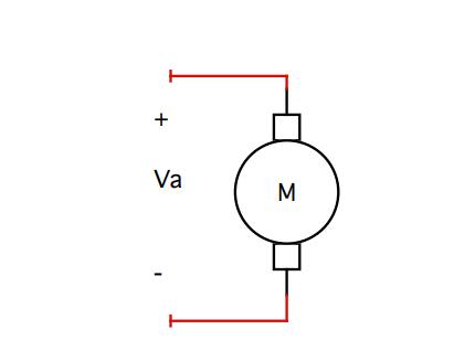
A DC motor is an actuator that converts electrical energy to mechanical rotation using the principles of electromagnetism. The circuit symbol for a DC motor is shown in the figure.
The learning objectives of this article are:
 Circuit Theory Model
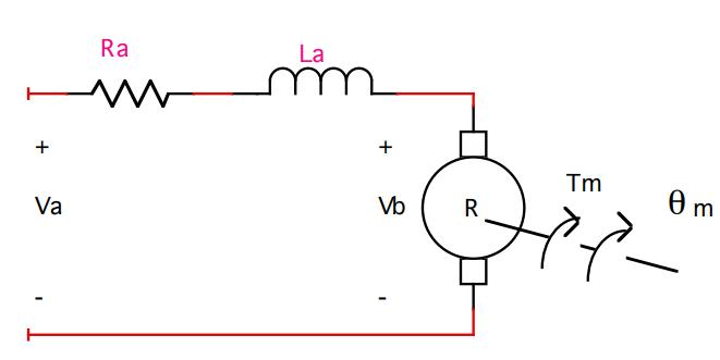
The circuit shown in the figure models the DC servomotor. Note that an armature control current is created when the armature control voltage, Va, energizes the motor. The current flow through a series-connected armature resistance, an armature inductance, and the rotational component (the rotor) of the motor. The rotor shaft is typically drawn to the right with the torque (Tm) and angular displacement (θm) variables shown. The motor transfer function is the ratio of angular displacement to armature voltage.
 Equations of Motion
Three equations of motion are fundamental to the derivation of the transfer function. Relationships between torque and current, voltage and angular displacement, and torque and system inertias are used. Torque is proportional to the armature current. The constant of proportionality is called the torque constant mand is given the symbol Kt. The time and frequency domain relationships are given as equations 1a and 1b.
The back electromotive force (back-emf), Vb, is a result of the rotor spinning at right angles in a magnetic field. It is proportional to the shaft velocity. The constant of proportionality is called the back-emf constant and is given the symbol Kb. The time and frequency domain relationships are given as equations 2a and 2b.
 Draw The DC Servo Motor Block Diagram
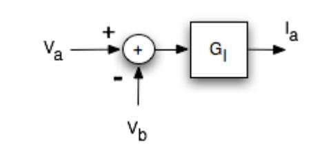
The DC servomotor transfer function block diagram can be created through an examination of the armature current equation. Ohm’s law for impedances is used to write the armature current equation in the s-domain. Note that the equation includes both real and imaginary parts of the impedance. The reactance is inductive. The figure shows the block diagram model of this equation.
 Similarly, the equations of motion can be used to relate the armature current to torque, torque to angular displacement, and angular displacement to the back-emf. The complete block diagram is shown in the figure.
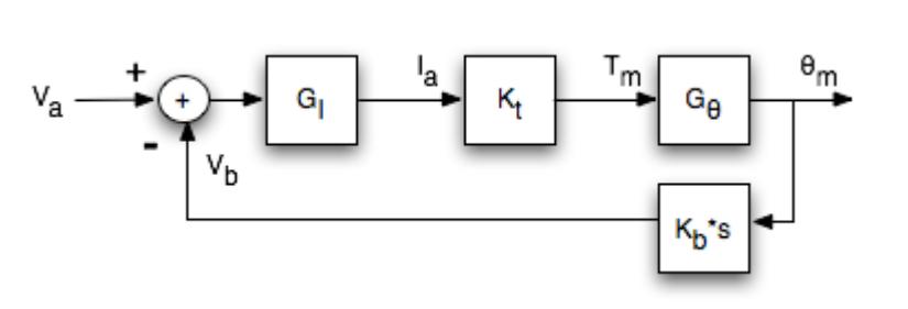
Note that this actuator is a feedback system that can be reduced to the standard form for derivation of the gain. The series gain path is reduced to an equivalent gain through multiplication. The reduced block diagram is shown in the figure. The forward path gain is traditionally called G while the feedback path gain is H.
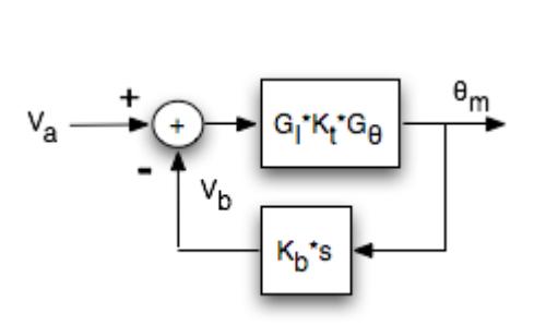 Derive The Transfer Function
The gain can be calculated directly from the reduced block diagram. Note that the denominator contains a + sign because the block diagram has negative feedback at the summation node. The denominator would contain a - sign if the block diagram used positive feedback. Remember, the denominator sign is opposite the feedback sign on the block diagram.
A DC motor is an actuator that converts electrical energy to mechanical rotation using the principles of electromagnetism. The circuit symbol for a DC motor is shown in the figure.
The learning objectives of this article are:
- Draw the equivalent DC servomotor circuit theory model.
- State the equations of motion used to derive the electromechanical transfer function in the time domain and the s-domain.
- Draw the DC servomotor signal block diagram.
- Derive the DC servomotor electromechanical transfer function.

The circuit shown in the figure models the DC servomotor. Note that an armature control current is created when the armature control voltage, Va, energizes the motor. The current flow through a series-connected armature resistance, an armature inductance, and the rotational component (the rotor) of the motor. The rotor shaft is typically drawn to the right with the torque (Tm) and angular displacement (θm) variables shown. The motor transfer function is the ratio of angular displacement to armature voltage.

Three equations of motion are fundamental to the derivation of the transfer function. Relationships between torque and current, voltage and angular displacement, and torque and system inertias are used. Torque is proportional to the armature current. The constant of proportionality is called the torque constant mand is given the symbol Kt. The time and frequency domain relationships are given as equations 1a and 1b.
(1a) Tm(t)=Kt*Ia(t)
(1b) Tm(s)=Kt*Ia(s)
The back electromotive force (back-emf), Vb, is a result of the rotor spinning at right angles in a magnetic field. It is proportional to the shaft velocity. The constant of proportionality is called the back-emf constant and is given the symbol Kb. The time and frequency domain relationships are given as equations 2a and 2b.
(2a) Vb(t)=Kb*dθm/dt
(2b) Vb(s)=Kb*sθm(s)
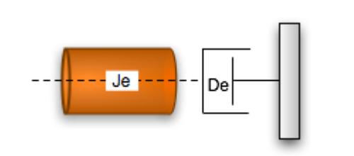
Torque can also be written as a relationship that depends on the load attached to the motor shaft. If the load inertial and damping behaviors are reflected back to the shaft the resulting equivalent inertia coefficient and viscous damping coefficient can be used to model the mechanical system attached to the shaft. These equivalents combine the motor and load properties in a model with a single degree of freedom. The figure diagrams the equivalent system. The torque equation can be written by inspection by summing the forces acting at the shaft.(2b) Vb(s)=Kb*sθm(s)
Tm=(Je*s2+De*s)θm
Gθ=1/Je*s2+De*s
Gθ=1/Je*s2+De*s

The DC servomotor transfer function block diagram can be created through an examination of the armature current equation. Ohm’s law for impedances is used to write the armature current equation in the s-domain. Note that the equation includes both real and imaginary parts of the impedance. The reactance is inductive. The figure shows the block diagram model of this equation.


The gain can be calculated directly from the reduced block diagram. Note that the denominator contains a + sign because the block diagram has negative feedback at the summation node. The denominator would contain a - sign if the block diagram used positive feedback. Remember, the denominator sign is opposite the feedback sign on the block diagram.
Post a Comment:
You may also like:
Category
Featured Articles
What is a Servo Motor?
 There are some special types of application of electrical motor where rotation of the motor is required for just a certain angle ...
 There are some special types of application of electrical motor where rotation of the motor is required for just a certain angle ...
What are the Basics of Servo Drive?
 Servo motors come in so many types and flavors that it is difficult to define them in a way that is accurate and universally ...
 Servo motors come in so many types and flavors that it is difficult to define them in a way that is accurate and universally ...
Why Use Servo Motor as Test Load?
 Dynamometer is mainly divided into two parts: cabinet and frame, while the frame mainly has the motor under test, torque speed ...
 Dynamometer is mainly divided into two parts: cabinet and frame, while the frame mainly has the motor under test, torque speed ...
What Should Consider Before Using ...
 Servo system is a commonly used control system, widely used in industrial automation. It compares the output signal with the ...
 Servo system is a commonly used control system, widely used in industrial automation. It compares the output signal with the ...
Servo Motor in Food Industry
 In the ever-evolving landscape of the food industry, technological advancements play a pivotal role in enhancing efficiency, ...
 In the ever-evolving landscape of the food industry, technological advancements play a pivotal role in enhancing efficiency, ...