Home » Servo Drive » Connected Servo Drive Using Fast Current Loop
Connected Servo Drive Using Fast Current Loop
Modern AC servo drives, depending on the end application, need high-bandwidth current control and speed control to enable superior performance, such as in CNC machines or in fast and precision control applications. With the Microcontroller unit (MCU), due to its higher level of integration, it is possible to implement fast current loop (FCL) algorithms that provide a high current loop bandwidth with the same external hardware as used in classical Field-Oriented Control methods.
Current Loops in Servo Drives
Two motor phase currents are measured. These measurements feed the transformation module. The outputs of this projection are designated isα and isβ. These two components of the current along with the rotor flux position are the inputs of the Park transformation, which transform them to currents (isd and isq) in d and q rotating reference frame. The isd and isq components are compared to the references isdref (the flux reference) and isqref (the torque reference).
At this point, the control structure shows an interesting advantage; it can be used to control either synchronous or asynchronous machines by simply changing the flux reference and obtaining the servo rotor flux position. In the synchronous permanent magnet motor, the rotor flux is fixed as determined by the magnets, so there is no need to create it. Therefore, when controlling a electric servo motor, isdref can be set to zero, except during field weakening.

Because servo motors need a rotor flux creation to operate, the flux reference must not be zero. This conveniently solves one of the major drawbacks of the classic control structures: the portability from asynchronous to synchronous drives. The torque command isqref can be connected to the output of the speed regulator. The outputs of the current regulators are Vsdref and Vsqref. These outputs are applied to the inverse Park transformation. Using the position of rotor flux, this projection generates Vsαref and Vsβref, which are the components of the stator vector voltage in the stationary orthogonal reference frame. These components are the inputs of the Space Vector PWM. The outputs of this block are the signals that drive the inverter.
Outline of the Fast Current Loop Library
The major challenge in digital motor control systems is the influence of sample and hold, as well as transportation lag inside the loop that slows down the system, impacting its performance at higher frequencies and running speeds. Fixing this problem will improve the current loop bandwidth. However, to achieve this without losing out on DC bus utilization, the following are necessary:
●High computational power
●The correct set of control peripherals
●Superior control algorithm
To make the current loop faster and to improve the operational range of current loops, the latency between feedback sampling and the PWM update must be as small as possible. It shows a PWM carrier cycle where system sampling is done at the carrier peak and the corresponding PWM update resulting from its control action is happening after a time TPWM_ update.
This substantially reduces the transportation lag and improves the bandwidth. However, the downside is the loss of the active PWM time window that is spent in computing the new values of PWM duty cycles for the inverter.
This is called the blanking window. The lower this blanking window, the higher the DC bus utilization and the operating speed range of the motor.

Typically, a latency of 2 μs or less is considered acceptable in many applications where the carrier frequency is 10 KHz. Traditionally, this task is implemented using a combination of high-end Field Programmable Gate Array (FPGAs), external Analog-to-Digital Converter (ADCs), and Microcontroller Unit (MCUs). However, due to the availability of hardware support such as trigonometric math unit (TMU), high-speed ADC or Filter Module, single cycle ADC read and PWM write, it is possible to implement this control on this MCU without FPGAs or external ADCs.
Filter Module
High-resolution, accurate, isolated phase current measurement is vital in automotive traction and servo drive applications, where high-performance torque and motion control are required. The options available for phase-current measurements are to use Hall-effect sensors, flux-gate sensors, current transformers, and shunt resistors.
The first three options have inherent galvanic isolation benefits and a high current measurement range, but the linearity, bandwidth, and drift are of lower performance when compared to the shunt-resistor option. Shunt resistors provide a highly linear, high-bandwidth, and cost-effective measurement solution. Reinforced isolation provides both benefits of isolation and high linearity and bandwidth. Isolated shunt-based current measurement is accomplished either by using an isolated amplifier or an isolated modulator.
There are two paths implemented in the design, the high-speed bit stream output from the isolated modulators is filtered by family real-time controllers that have a built-in filter module, allowing the user to fine-tune signal bandwidth and accuracy.
The filter module is a four-channel digital filter designed specifically for current measurement in motor control applications. Each channel can receive an independent delta-sigma modulator bit stream which is processed by four individually programmable digital decimation filters. The filters include a fast comparator for immediate digital threshold comparisons for over-current and undercurrent monitoring.
Also, a filter-bypass mode is available to enable data logging, analysis, and customized filtering. The filter module pins are configured using the multiplexer. A key benefit of the filter module is it enables a simple, cost-effective, and safe high-voltage isolation boundary.
Current Loops in Servo Drives
Two motor phase currents are measured. These measurements feed the transformation module. The outputs of this projection are designated isα and isβ. These two components of the current along with the rotor flux position are the inputs of the Park transformation, which transform them to currents (isd and isq) in d and q rotating reference frame. The isd and isq components are compared to the references isdref (the flux reference) and isqref (the torque reference).
At this point, the control structure shows an interesting advantage; it can be used to control either synchronous or asynchronous machines by simply changing the flux reference and obtaining the servo rotor flux position. In the synchronous permanent magnet motor, the rotor flux is fixed as determined by the magnets, so there is no need to create it. Therefore, when controlling a electric servo motor, isdref can be set to zero, except during field weakening.
Because servo motors need a rotor flux creation to operate, the flux reference must not be zero. This conveniently solves one of the major drawbacks of the classic control structures: the portability from asynchronous to synchronous drives. The torque command isqref can be connected to the output of the speed regulator. The outputs of the current regulators are Vsdref and Vsqref. These outputs are applied to the inverse Park transformation. Using the position of rotor flux, this projection generates Vsαref and Vsβref, which are the components of the stator vector voltage in the stationary orthogonal reference frame. These components are the inputs of the Space Vector PWM. The outputs of this block are the signals that drive the inverter.
Outline of the Fast Current Loop Library
The major challenge in digital motor control systems is the influence of sample and hold, as well as transportation lag inside the loop that slows down the system, impacting its performance at higher frequencies and running speeds. Fixing this problem will improve the current loop bandwidth. However, to achieve this without losing out on DC bus utilization, the following are necessary:
●High computational power
●The correct set of control peripherals
●Superior control algorithm
To make the current loop faster and to improve the operational range of current loops, the latency between feedback sampling and the PWM update must be as small as possible. It shows a PWM carrier cycle where system sampling is done at the carrier peak and the corresponding PWM update resulting from its control action is happening after a time TPWM_ update.
This substantially reduces the transportation lag and improves the bandwidth. However, the downside is the loss of the active PWM time window that is spent in computing the new values of PWM duty cycles for the inverter.
This is called the blanking window. The lower this blanking window, the higher the DC bus utilization and the operating speed range of the motor.
Filter Module
High-resolution, accurate, isolated phase current measurement is vital in automotive traction and servo drive applications, where high-performance torque and motion control are required. The options available for phase-current measurements are to use Hall-effect sensors, flux-gate sensors, current transformers, and shunt resistors.
The first three options have inherent galvanic isolation benefits and a high current measurement range, but the linearity, bandwidth, and drift are of lower performance when compared to the shunt-resistor option. Shunt resistors provide a highly linear, high-bandwidth, and cost-effective measurement solution. Reinforced isolation provides both benefits of isolation and high linearity and bandwidth. Isolated shunt-based current measurement is accomplished either by using an isolated amplifier or an isolated modulator.
There are two paths implemented in the design, the high-speed bit stream output from the isolated modulators is filtered by family real-time controllers that have a built-in filter module, allowing the user to fine-tune signal bandwidth and accuracy.
The filter module is a four-channel digital filter designed specifically for current measurement in motor control applications. Each channel can receive an independent delta-sigma modulator bit stream which is processed by four individually programmable digital decimation filters. The filters include a fast comparator for immediate digital threshold comparisons for over-current and undercurrent monitoring.
Also, a filter-bypass mode is available to enable data logging, analysis, and customized filtering. The filter module pins are configured using the multiplexer. A key benefit of the filter module is it enables a simple, cost-effective, and safe high-voltage isolation boundary.
Post a Comment:
You may also like:
Category
Featured Articles
What are the Soft Start Techniques for ...
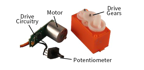 Servos (as commonly used in radio-controlled vehicles and small-scale robotics)are DC actuators that use a potentiometer to ...
Servos (as commonly used in radio-controlled vehicles and small-scale robotics)are DC actuators that use a potentiometer to ...Servo Drive System vs. Variable ...
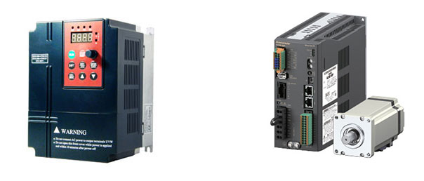 A servo drive system, as opposed to a variable frequency drive (VFD) or AC motor drive , has the ability to position with ...
A servo drive system, as opposed to a variable frequency drive (VFD) or AC motor drive , has the ability to position with ...What are the Basics of Servo Drive?
 Servo motors come in so many types and flavors that it is difficult to define them in a way that is accurate and universally ...
Servo motors come in so many types and flavors that it is difficult to define them in a way that is accurate and universally ...How to Install a Servo Drive?
 Installing a servo drive involves several steps, and the specific process may vary depending on the manufacturer and model of the ...
Installing a servo drive involves several steps, and the specific process may vary depending on the manufacturer and model of the ...