Home » Servo System » Research on Servo System of Hydraulic Servo Cylinder Test Bed
Research on Servo System of Hydraulic Servo Cylinder Test Bed
Hydraulic cylinder test and detection is an
important means to guarantee the normal work of the hydraulic system. Due to
the traditional hydraulic cylinder test bed has the problem of low accuracy and
low working efficiency, therefore, an accurate detection and intelligent
hydraulic cylinder test-bed is the developing direction in the future.
The hydraulic cylinder test bed adopts the servo control system, using industrial computer as the upper machine, responsible for analog acquisition, data storage; using the PLC as lower machine, responsible for the control of the action logic of hydraulic components; also used touch screen as the auxiliary equipment. The servo system improved the system accuracy, automation and system stability.
The servo system
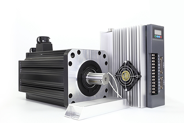
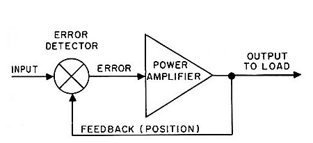
The servo system is composed of hydraulic pump, electro hydraulic servo valve, proportional relief valve and pressure sensor and so on. The electro hydraulic servo valve, proportional relief valve and pressure sensor formed pressure closed loop control.
The pressure sensor detect the pressure value of the hydraulic cylinder port, and send the signal to PLC by AD module. Then the PLC putout control signal after calculating. The signal is converted into voltage signal by D/A module. In the end the voltage signal is amplified by the servo amplifier to control the opening of electro hydraulic servo valve and proportional relief valve to control the pressure of the system.
Control system structure design
The control system is mainly composed of input switches, limit switches, pressure sensor, data acquisition, industrial computer, PLC controller, touch screen, switch output, analog output, as shown in the following picture.
The system contains both digital and analog, data acquisition is divided into two parts, PLC is responsible for the collection of digital quantity such as switch button, limit switch etc. The data acquisition card is responsible for the collection of analog signal such as temperature and pressure sensor signal. Industrial computer is responsible for data processing, analysis, calculation, table storage and so on.
The touch screen is mainly used for manual operation, servo parameter setting, test item selection and test curve display and so on. PLC as the core controller is responsible for all kinds of switch quantity input and output and analog output and controls the logical sequence of each component of the hydraulic system.
PLC type selection and I/O distribution
Control system selected S7-200 series PLC, according to the experimental requirements, the system has 13 switch input points and output points 6; analog input point 2 and the output point 2. So choose an analog expansion module 4 input and 2 output, and finally matched with a Touchscreen.
Control system software design
The control program is divided into manual and automatic modes. Taking into account the scalability of the program, this paper uses the modular design method. According to the functional requirements of the hydraulic test bench is divided into the following modules: main program, parameter setting module, user module, data acquisition module, communication module, data storage module, operation module and test system module.
The PLC program design
Open the system, enter the login page for authentication, if right enter the system or exit the system, then load the test parameters and ask for industrial computer to start the experiment. At the same time, the hydraulic system initialization, when the two meet began to test selection and test, test is completed choose whether or not to keep the test report.
Several main test automation program implementation process
The hydraulic cylinder test bed adopts the servo control system, using industrial computer as the upper machine, responsible for analog acquisition, data storage; using the PLC as lower machine, responsible for the control of the action logic of hydraulic components; also used touch screen as the auxiliary equipment. The servo system improved the system accuracy, automation and system stability.
The servo system
The servo system is composed of hydraulic pump, electro hydraulic servo valve, proportional relief valve and pressure sensor and so on. The electro hydraulic servo valve, proportional relief valve and pressure sensor formed pressure closed loop control.
The pressure sensor detect the pressure value of the hydraulic cylinder port, and send the signal to PLC by AD module. Then the PLC putout control signal after calculating. The signal is converted into voltage signal by D/A module. In the end the voltage signal is amplified by the servo amplifier to control the opening of electro hydraulic servo valve and proportional relief valve to control the pressure of the system.
Control system structure design
The control system is mainly composed of input switches, limit switches, pressure sensor, data acquisition, industrial computer, PLC controller, touch screen, switch output, analog output, as shown in the following picture.
The system contains both digital and analog, data acquisition is divided into two parts, PLC is responsible for the collection of digital quantity such as switch button, limit switch etc. The data acquisition card is responsible for the collection of analog signal such as temperature and pressure sensor signal. Industrial computer is responsible for data processing, analysis, calculation, table storage and so on.
The touch screen is mainly used for manual operation, servo parameter setting, test item selection and test curve display and so on. PLC as the core controller is responsible for all kinds of switch quantity input and output and analog output and controls the logical sequence of each component of the hydraulic system.
PLC type selection and I/O distribution
Control system selected S7-200 series PLC, according to the experimental requirements, the system has 13 switch input points and output points 6; analog input point 2 and the output point 2. So choose an analog expansion module 4 input and 2 output, and finally matched with a Touchscreen.
Control system software design
The control program is divided into manual and automatic modes. Taking into account the scalability of the program, this paper uses the modular design method. According to the functional requirements of the hydraulic test bench is divided into the following modules: main program, parameter setting module, user module, data acquisition module, communication module, data storage module, operation module and test system module.
The PLC program design
Open the system, enter the login page for authentication, if right enter the system or exit the system, then load the test parameters and ask for industrial computer to start the experiment. At the same time, the hydraulic system initialization, when the two meet began to test selection and test, test is completed choose whether or not to keep the test report.
Several main test automation program implementation process
- Trial run test. First hydraulic power units started, then 2YA energized ,the piston shift right; when the piston rod reaches the right end, right limit switch emit commutation signals, 1YA energized, the piston shift left; when the piston rod reaches the left end, left limit switch emit commutation signals, cycle more than five times, use PLC internal counter to count. Hydraulic cylinder should operate smoothly and can’t have leakage.
- Start-up pressure test. First hydraulic power units started, then 2YA energized, the piston shift right; when the photoelectric switch detected the hydraulic cylinder piston rod, 1YA energized, the piston shift left, when the piston rod reaches the left end, left limit switch emit signals, the test is completed. The pressure sensor is used to record all changes in pressure and the maximum value is the starting pressure.
- Durability test. First set the proportional relief valve pressure for the nominal pressure, then hydraulic power units started, 2YA energized, the piston shift right; when the piston rod reaches the right end, right limit switch emit commutation signals, 1YA energized, the piston shift left; when the piston rod reaches the left end, left limit switch emit commutation signals, cycle more than five thousand times.
Post a Comment:
You may also like:
Category
Featured Articles
What is Servo System?
 A feedback control system used to precisely follow or reproduce a process. Also known as a follower system. In many cases, a ...
A feedback control system used to precisely follow or reproduce a process. Also known as a follower system. In many cases, a ...What Should Consider Before Using ...
 Servo system is a commonly used control system, widely used in industrial automation. It compares the output signal with the ...
Servo system is a commonly used control system, widely used in industrial automation. It compares the output signal with the ...What is the Bandwidth of ...
 For a servo system, the bandwidth is the maximum sine wave frequency to which the servo system can respond. In professional ...
For a servo system, the bandwidth is the maximum sine wave frequency to which the servo system can respond. In professional ...What are the Basic Components of ...
 Servomechanisms, called servos for short, are the basic building blocks of power drives. In this manual what we mean by a power ...
Servomechanisms, called servos for short, are the basic building blocks of power drives. In this manual what we mean by a power ...